Toyota 4Runner: Reassembly
REASSEMBLY
CAUTION / NOTICE / HINT
HINT:
- Use the same procedure for the RH and LH sides.
- The procedures listed below are for the LH side.
PROCEDURE
1. INSTALL PARKING BRAKE SHOE HOLD DOWN SPRING PIN
(a) Install the parking brake shoe hold down spring pin (for front side).
(b) Install the parking brake shoe hold down spring pin (for rear side).
2. APPLY HIGH-TEMPERATURE GREASE
|
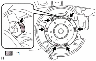
(a) Apply a light coat of high-temperature grease to the areas of the backing plate which make contact with the shoe as shown in the illustration. Text in Illustration
|
|
3. INSTALL PARKING BRAKE SHOE LEVER
(a) Apply a light coat of high-temperature grease to the areas of the parking brake shoe lever which make contact with the No. 2 parking brake shoe assembly.
|
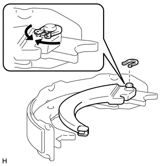
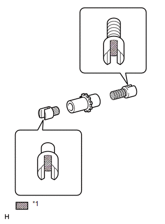
(b) Install the parking brake shoe lever and shim to the No. 2 parking brake shoe assembly with a new C-washer as shown in the illustration. |
|
|
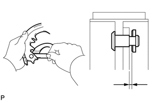
(c) Using a feeler gauge, measure the clearance between the No. 2 parking brake shoe assembly and parking brake shoe lever. Standard clearance: Less than 0.25 mm (0.00984 in.) If the clearance is not within the specification, replace the shim with one of a different thickness so that the clearance is within the specification. Standard Shim:
|
|
4. INSTALL NO. 2 PARKING BRAKE SHOE ASSEMBLY WITH PARKING BRAKE SHOE LEVER
|
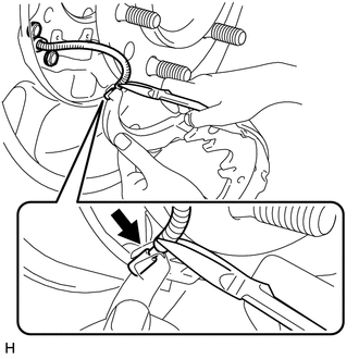
(a) Using needle-nose pliers, connect the No. 3 parking brake cable assembly to the parking brake shoe lever as shown in the illustration. NOTICE: Be careful not to damage the No. 3 parking brake cable assembly. |
|
5. INSTALL PARKING BRAKE SHOE RETURN TENSION SPRING
(a) Install the parking brake shoe return tension spring to the No. 2 parking brake shoe assembly.
6. INSTALL NO. 1 PARKING BRAKE SHOE ASSEMBLY LH
(a) Connect the parking brake shoe return tension spring to install the No. 1 parking brake shoe assembly.
7. INSTALL PARKING BRAKE SHOE ADJUSTING SCREW SET
|
(a) Apply a light coat of high-temperature grease to the areas of the shoe adjusting screw set shown in the illustration. Text in Illustration
|
|
(b) Install the parking brake shoe adjusting screw set.
8. INSTALL NO. 2 PARKING BRAKE SHOE ASSEMBLY LH
(a) Install the No. 2 parking brake shoe assembly to the backing plate with the parking brake shoe hold down spring cup and parking brake shoe hold down spring.
9. INSTALL PARKING BRAKE SHOE STRUT
(a) Install the parking brake shoe strut and parking brake shoe strut compression spring.
10. INSTALL NO. 1 PARKING BRAKE SHOE ASSEMBLY LH
(a) Install the No. 1 parking brake shoe assembly to the backing plate with the parking brake shoe hold down spring cup and parking brake shoe hold down spring.
11. INSTALL PARKING BRAKE SHOE RETURN TENSION SPRING
(a) Install the 2 parking brake shoe return tension springs.
HINT:
First install the front side spring, and then the rear side spring.
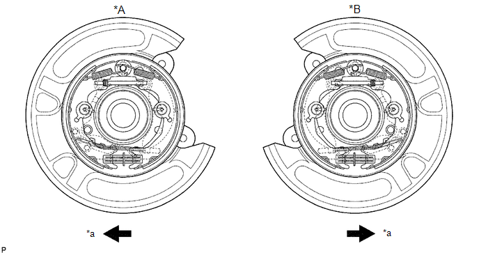
12. CHECK PARKING BRAKE INSTALLATION
 Text in Illustration
|
*A |
LH |
*B |
RH |
|
*a |
Front |
- |
- |
(a) Check that each part is installed properly.
NOTICE:
There should be no oil or grease adhering to the friction surfaces of the shoe lining and disc.
13. INSTALL REAR DISC
.gif)
14. CONNECT REAR DISC BRAKE CYLINDER ASSEMBLY LH
(a) Connect the rear disc brake cylinder with the 2 bolts.
Torque:
105 N·m {1071 kgf·cm, 77 ft·lbf}
15. ADJUST PARKING BRAKE SHOE CLEARANCE AND PARKING BRAKE PEDAL TRAVEL
16. INSPECT PARKING BRAKE PEDAL TRAVEL
17. INSTALL REAR WHEEL
18. SETTLE PARKING BRAKE SHOE AND DISC
(a) Drive the vehicle for approximately 400 m (0.25 miles) under the following conditions.
(1) The vehicle speed is approximately 50 km/h (31 mph) and the vehicle is on a safe, level and dry road.
(2) The parking brake pedal is being depressed with a force of 150 N (15 kgf, 33.7 ldf).
NOTICE:
Set a 5-minute interval between each procedure to prevent the brake assembly from overheating.
 Inspection
INSPECTION
PROCEDURE
1. CHECK BRAKE DISC INSIDE DIAMETER
(a) Using a brake drum gauge or equivalent, measure the inside diameter
of the disc.
Standard inside diameter:
210 mm ...

Other materials about Toyota 4Runner:
Installation
INSTALLATION
PROCEDURE
1. INSTALL POWER WINDOW REGULATOR MOTOR ASSEMBLY LH
NOTICE:
The regulator arm must be below the intermediate position when installing the
rear power window regulator motor assembly.
(a) Using a T25 "TORX" sock ...
Seat Memory Switch
Components
COMPONENTS
ILLUSTRATION
Removal
REMOVAL
PROCEDURE
1. REMOVE FRONT DOOR LOWER FRAME BRACKET GARNISH LH
2. REMOVE NO. 2 DOOR INSIDE HANDLE BEZEL LH
3. REMOVE FRONT DOOR TRIM BOARD SUB-ASSEMBLY LH
4. REMOVE FRONT DOOR INNER GLAS ...

0.0112