Toyota 4Runner: Removal
REMOVAL
PROCEDURE
1. DISCONNECT CABLE FROM NEGATIVE BATTERY TERMINAL
CAUTION:
Wait at least 90 seconds after disconnecting the cable from the negative (-)
battery terminal to disable the SRS system (See page
.gif) ).
).
NOTICE:
When disconnecting the cable, some systems need to be initialized after the cable
is reconnected (See page ).
2. REMOVE DOOR SCUFF PLATE ASSEMBLY LH
3. REMOVE COWL SIDE TRIM BOARD LH
4. REMOVE NO. 1 INSTRUMENT CLUSTER FINISH PANEL GARNISH
5. REMOVE LOWER INSTRUMENT PANEL FINISH PANEL SUB-ASSEMBLY
6. REMOVE LOWER NO. 1 INSTRUMENT PANEL AIRBAG ASSEMBLY
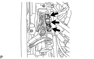
7. REMOVE DRIVER SIDE JUNCTION BLOCK ASSEMBLY
|
(a) Disconnect the 3 connectors. |
|
|
(b) Disconnect the 2 connectors labeled (1) as shown in the illustration. |
|
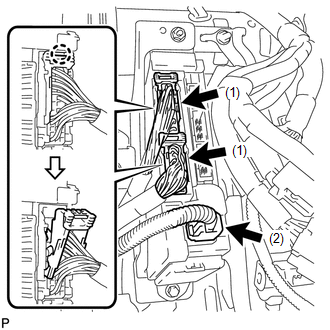
(c) Disconnect the connector labeled (2).
|
(d) Remove the bolt and 2 nuts and disconnect the driver side junction block assembly. |
|
|
(e) Detach the claw and disconnect the connector as shown in the illustration. |
|
|
(f) Detach the 2 claws and release the connector's lock as shown in the illustration. |
|
|
(g) Detach the claw and disconnect the connector as shown in the illustration. |
|
(h) Remove the driver side junction block assembly.
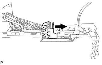
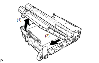
8. REMOVE MULTIPLEX NETWORK BODY ECU
|
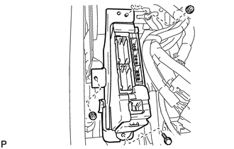
(a) Press the claw of the junction block as shown in the illustration to release the lock. Text in Illustration
|
|
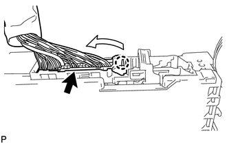
(b) With the junction block lock released, insert a screwdriver with its tip wrapped with protective tape horizontally between the multiplex network body ECU and junction block.
NOTICE:
Use a screwdriver with a radius of between 5.0 mm (0.197 in.) and 6.3 mm (0.248 in.) and a length of approximately 90 mm (3.54 in.).
|
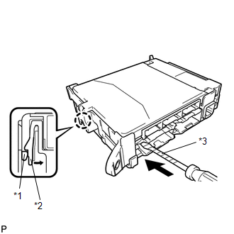
(c) Using the screwdriver, carefully raise the multiplex network body ECU until the connector becomes disengaged. NOTICE: Do not twist the screwdriver to raise the multiplex network body ECU. |
|
|
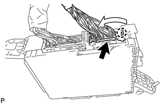
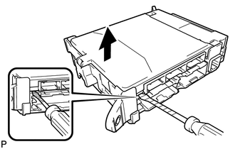
(d) Raise the multiplex network body ECU as shown by arrow (1), and then pull it out as shown by arrow (2) in the illustration. NOTICE: Do not touch the ECU connector. |
|
 Components
COMPONENTS
ILLUSTRATION
...
 Installation
INSTALLATION
CAUTION / NOTICE / HINT
HINT:
A bolt without a torque specification is shown in the standard bolt chart (See
page ).
PROCEDURE
1. INSTALL MULTIPLEX NETWORK BODY ECU
NOTICE:
...
Other materials about Toyota 4Runner:
Problem Symptoms Table
PROBLEM SYMPTOMS TABLE
HINT:
Use the table below to help determine the cause of problem symptoms. If multiple
suspected areas are listed, the potential causes of the symptoms are listed in order
of probability in the "Suspected Area" column of ...
Removal
REMOVAL
CAUTION / NOTICE / HINT
CAUTION:
Wear protective gloves. Sharp areas on the parts may injure your hands.
PROCEDURE
1. REMOVE REAR SEAT ASSEMBLY RH
(a) Remove the rear No. 1 seat assembly RH (See page
).
2. REMOVE NO. 1 SEATBACK BOARD SUB-ASSEM ...

0.0274