Toyota 4Runner: Installation
INSTALLATION
CAUTION / NOTICE / HINT
HINT:
A bolt without a torque specification is shown in the standard bolt chart (See
page .gif) ).
).
PROCEDURE
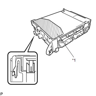
1. INSTALL MULTIPLEX NETWORK BODY ECU
NOTICE:
- Make sure that no foreign objects contact the connecting surfaces.
- Do not touch the ECU connector.
|
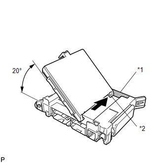
(a) Insert the multiplex network body ECU until it contacts the housing sidewall of the guide part as shown in the illustration. Text in Illustration
HINT: Be sure to maintain an angle of 20° or more as shown in the illustration. |
|
|
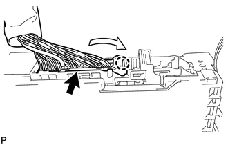
(b) Slide the guide of the multiplex network body ECU along the housing sidewall toward the junction block fuses as shown in the illustration. Text in Illustration
|
|
|
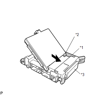
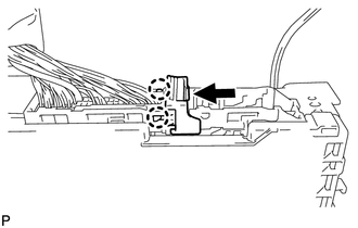
(c) Slide the multiplex network body ECU so that it contacts side A as shown in the illustration. Text in Illustration
NOTICE: Do not apply excessive force to the multiplex network body ECU. |
|
|
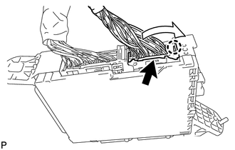
(d) With the multiplex network body ECU contacting side A of the junction block (point of rotation), rotate it downward as shown in the illustration. Text in Illustration
|
|
|
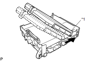
(e) Press the pushing area until the claw attaches to install the multiplex network body ECU. Text in Illustration
NOTICE:
HINT: If a lock sound cannot be heard, visually check the engagement of the lock part. The engagement can also be confirmed if the multiplex network body ECU and junction block are flush. |
|
2. INSTALL DRIVER SIDE JUNCTION BLOCK ASSEMBLY
|
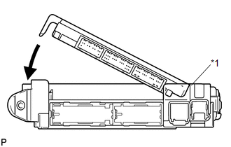
(a) Attach the claw to install the connector as shown in the illustration. NOTICE: Be sure to connect each connector securely. |
|
|
(b) Attach the 2 claws to lock the connector lock as shown in the illustration. |
|
|
(c) Attach the claw to connect the connector as shown in the illustration. NOTICE: Be sure to connect the connector securely. |
|
(d) Install the driver side junction block assembly with the bolt and 2 nuts.
Torque:
for Bolt :
13 N·m {133 kgf·cm, 10 ft·lbf}
for Nut :
8.0 N·m {82 kgf·cm, 71 in·lbf}
|
(e) Connect the connector labeled (2). NOTICE: Be sure to connect each connector securely. |
|
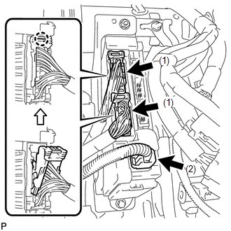
(f) Connect the 2 connectors labeled (1) as shown in the illustration.
NOTICE:
Be sure to connect each connector securely.
(g) Connect the 3 connectors.
NOTICE:
Be sure to connect each connector securely.
3. INSTALL LOWER NO. 1 INSTRUMENT PANEL AIRBAG ASSEMBLY
4. INSTALL LOWER INSTRUMENT PANEL FINISH PANEL SUB-ASSEMBLY
5. INSTALL NO. 1 INSTRUMENT CLUSTER FINISH PANEL GARNISH
6. INSTALL COWL SIDE TRIM BOARD LH
7. INSTALL DOOR SCUFF PLATE ASSEMBLY LH
8. CONNECT CABLE TO NEGATIVE BATTERY TERMINAL
NOTICE:
When disconnecting the cable, some systems need to be initialized after the cable
is reconnected (See page ).
9. CHECK SRS WARNING LIGHT
(a) Check the SRS warning light (See page ).
 Removal
REMOVAL
PROCEDURE
1. DISCONNECT CABLE FROM NEGATIVE BATTERY TERMINAL
CAUTION:
Wait at least 90 seconds after disconnecting the cable from the negative (-)
battery terminal to disable the SRS sys ...

Other materials about Toyota 4Runner:
Removal
REMOVAL
CAUTION / NOTICE / HINT
HINT:
Use the same procedure for the RH and LH sides.
The procedure listed below is for the LH side.
PROCEDURE
1. DISCONNECT CABLE FROM NEGATIVE BATTERY TERMINAL
CAUTION:
Wait at least 90 seconds after d ...
Installation
INSTALLATION
PROCEDURE
1. INSTALL WINDSHIELD WASHER MOTOR AND PUMP ASSEMBLY
(a) Install the windshield washer motor and pump assembly to the packing of the
washer jar.
2. INSTALL WASHER JAR
(a) Attach the guide to install the washer jar, and ...

0.0073