Toyota 4Runner: Removal
REMOVAL
CAUTION / NOTICE / HINT
HINT:
- Use the same procedure for the RH and LH sides.
- The procedure listed below is for the LH side.
- When removing the window frame moulding, heat the vehicle body and window
frame moulding using a heat light.
Standard:
Item
Temperature
Vehicle Body
40 to 60°C (104 to 140°F)
Window Frame Moulding
20 to 30°C (68 to 86°F)
NOTICE:
Do not heat the vehicle body or window frame moulding excessively.
PROCEDURE
1. DISCONNECT CABLE FROM NEGATIVE BATTERY TERMINAL
CAUTION:
Wait at least 90 seconds after disconnecting the cable from the negative (-) battery terminal to disable the SRS system.
NOTICE:
When disconnecting the cable, some systems need to be initialized after the cable
is reconnected (See page .gif) ).
).
2. REMOVE FRONT DOOR LOWER FRAME BRACKET GARNISH LH
3. REMOVE NO. 2 DOOR INSIDE HANDLE BEZEL LH
4. REMOVE FRONT DOOR TRIM BOARD SUB-ASSEMBLY LH
5. REMOVE FRONT DOOR INNER GLASS WEATHERSTRIP LH
6. REMOVE FRONT DOOR SERVICE HOLE COVER LH
7. REMOVE OUTER REAR VIEW MIRROR ASSEMBLY LH
8. REMOVE FRONT DOOR GLASS SUB-ASSEMBLY LH
9. REMOVE FRONT DOOR GLASS RUN LH
10. REMOVE FRONT DOOR BELT MOULDING LH
11. REMOVE FRONT DOOR WEATHERSTRIP LH
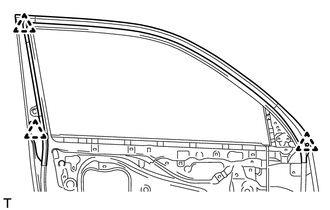
(a) Detach the 3 clips and remove the upper part of the front door weatherstrip so that the moulding can be removed.
12. REMOVE FRONT DOOR REAR WINDOW FRAME MOULDING LH
|
(a) Remove the door window frame moulding clip. |
|
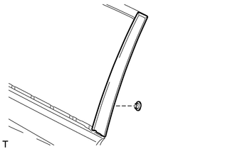
|
(b) Put protective tape around the front door rear window frame moulding. Text in Illustration
|
|
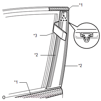
(c) Using a moulding remover, detach the clip and remove the double-sided tape to remove the front door rear window frame moulding.
 Components
COMPONENTS
ILLUSTRATION
ILLUSTRATION
ILLUSTRATION
...
 Installation
INSTALLATION
CAUTION / NOTICE / HINT
HINT:
Use the same procedure for the RH and LH sides.
The procedure listed below is for the LH side.
When installing the window frame moulding, ...
Other materials about Toyota 4Runner:
AVC-LAN Circuit
DESCRIPTION
Each unit of the navigation system connected to the AVC-LAN (communication bus)
transfers the switch signals using the AVC-LAN.
If a short to +B or short to ground occurs in the AVC-LAN, the navigation system
will not function normally becaus ...
Reassembly
REASSEMBLY
CAUTION / NOTICE / HINT
HINT:
Use the same procedure for both the RH and LH sides.
The procedure listed below is for the LH side.
PROCEDURE
1. INSTALL OUTER MIRROR LIGHT ASSEMBLY BULB (w/ Side Turn Signal Light)
(a) Install t ...

0.0069