Toyota 4Runner: Removal
REMOVAL
CAUTION / NOTICE / HINT
HINT:
- Use the same procedure for both the RH and LH sides.
- The procedure listed below is for the LH side.
PROCEDURE
1. REMOVE FRONT FENDER MUDGUARD LH (w/o Intuitive Parking Assist System)
.gif)
2. REMOVE FRONT FENDER MUDGUARD LH (w/ Intuitive Parking Assist System)
3. REMOVE ROCKER PANEL MOULDING COVER LH (w/o Intuitive Parking Assist System)
|
(a) Remove the screw. |
|
(b) Detach the 2 clips to remove the rocker panel moulding cover LH.
4. REMOVE ROCKER PANEL MOULDING LH (w/ Intuitive Parking Assist System)
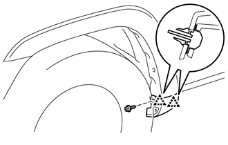
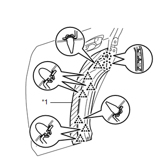
5. REMOVE FRONT FENDER MOULDING SUB-ASSEMBLY LH
|
(a) Put protective tape around the front fender moulding sub-assembly LH. Text in Illustration
|
|
(b) Remove the grommet.
(c) w/ Intuitive Parking Assist System:
(1) Remove the clip.
|
(d) Remove the 6 screws. |
|
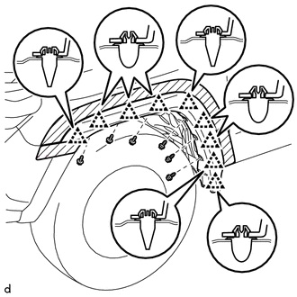
(e) Using a moulding remover, detach the 9 clips to remove the front fender moulding sub-assembly LH.
(f) Remove the 9 clips.
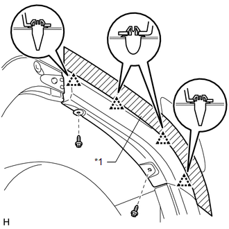
6. REMOVE REAR DOOR OUTSIDE MOULDING LH (w/o Intuitive Parking Assist System)
|
(a) Put protective tape around the rear door outside moulding LH. Text in Illustration
|
|
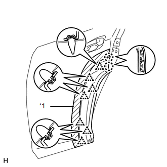
(b) Using a moulding remover, detach the 7 clips and 2 claws to remove the rear door outside moulding LH.
(c) Remove the 7 clips.
7. REMOVE REAR DOOR OUTSIDE MOULDING LH (w/ Intuitive Parking Assist System)
|
(a) Put protective tape around the rear door outside moulding LH. Text in Illustration
|
|
(b) Using a moulding remover, detach the 7 clips and 2 claws to remove the rear door outside moulding LH.
(c) Remove the 7 clips.
8. REMOVE NO. 3 OUTSIDE MOULDING RETAINER
|
(a) Remove the screw. |
|
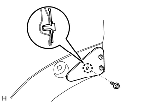
(b) Detach the claw to remove the No. 3 outside moulding retainer.
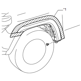
9. REMOVE REAR QUARTER OUTSIDE MOULDING LH
|
(a) Put protective tape around the rear quarter outside moulding LH. Text in Illustration
|
|
(b) Remove the 2 screws.
(c) Using a moulding remover, detach the 4 clips to remove the rear quarter outside moulding LH.
(d) Remove the 4 clips.
 Disassembly
DISASSEMBLY
CAUTION / NOTICE / HINT
HINT:
Use the same procedure for the RH and LH sides.
The procedure listed below is for the LH side.
PROCEDURE
1. REMOVE FRONT FENDER OUTSIDE ...
 Reassembly
REASSEMBLY
CAUTION / NOTICE / HINT
HINT:
Use the same procedure for the RH and LH sides.
The procedure listed below is for the LH side.
When installing the pad, heat the moulding su ...
Other materials about Toyota 4Runner:
IG Power Source Circuit
DESCRIPTION
The main power source is supplied to the air conditioning amplifier assembly
when the ignition switch is turned to ON. The power source is used for operating
the air conditioning amplifier assembly, servo motors, etc.
WIRING DIAGRAM
CAUTIO ...
On-vehicle Inspection
ON-VEHICLE INSPECTION
PROCEDURE
1. INSPECT VOLTAGE INVERTER ASSEMBLY
HINT:
Remove interior parts so that the voltage inverter can be seen.
(a) Disconnect the voltage inverter connector.
(b) Measur ...

0.0084