Toyota 4Runner: Removal
REMOVAL
PROCEDURE
1. DISCONNECT CABLE FROM NEGATIVE BATTERY TERMINAL
NOTICE:
When disconnecting the cable, some systems need to be initialized after the cable
is reconnected (See page .gif) ).
).
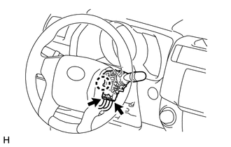
2. REMOVE LOWER STEERING COLUMN COVER
|
(a) Turn the steering wheel to the left and remove the screw. |
|
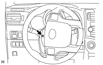
|
(b) Turn the steering wheel to the right and remove the screw. |
|
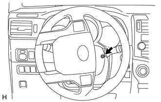
|
(c) Detach the 2 claws and remove the lower steering column cover. |
|
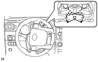
3. REMOVE UPPER STEERING COLUMN COVER
|
(a) Detach the 4 clips and claw and remove the steering column cover. |
|
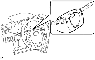
4. REMOVE WINDSHIELD WIPER SWITCH ASSEMBLY
|
(a) Disconnect the 2 connectors. |
|
(b) Detach the claw and remove the windshield wiper switch assembly.
 Components
COMPONENTS
ILLUSTRATION
...
 Inspection
INSPECTION
PROCEDURE
1. INSPECT WINDSHIELD WIPER SWITCH ASSEMBLY
(a) Measure the resistance according to the value(s) in the table below.
Standard Resistance:
Front Wiper Switch
...
Other materials about Toyota 4Runner:
Reassembly
REASSEMBLY
CAUTION / NOTICE / HINT
HINT:
When installing the rear spoiler protector, heat the rear spoiler surface using
a heat light.
Standard:
Item
Temperature
Rear Spoiler
20 to 30°C (68 to 86°F)
...
Clock
1. Adjusts the hours
2. Adjusts the minutes
For quicker adjustment of the clock
To advance the minutes and hours quickly, press and hold the “M” or “H”
button.
The time can be adjusted back or forth by following the procedure below:
The hou ...

0.0269