Toyota 4Runner: Removal
REMOVAL
PROCEDURE
1. REMOVE NO. 1 INSTRUMENT CLUSTER FINISH PANEL GARNISH
.gif)
2. REMOVE NO. 2 INSTRUMENT CLUSTER FINISH PANEL GARNISH
3. REMOVE HEATER CONTROL ASSEMBLY
4. REMOVE SHIFT LEVER KNOB SUB-ASSEMBLY
5. REMOVE SHIFT LEVER KNOB SUB-ASSEMBLY (for VF2A)
6. REMOVE UPPER CONSOLE PANEL SUB-ASSEMBLY
7. REMOVE NO. 2 CONSOLE BOX RETAINER
8. REMOVE LOWER CENTER INSTRUMENT CLUSTER FINISH PANEL SUB-ASSEMBLY (w/ Climate Control Seat System)
9. REMOVE LOWER CENTER INSTRUMENT CLUSTER FINISH PANEL SUB-ASSEMBLY (w/o Climate Control Seat System)
10. REMOVE POWER OUTLET SOCKET ASSEMBLY
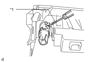
(a) Remove the power outlet socket assembly (w/ Climate Control Seat System).
|
(1) Using a screwdriver, detach the claw to remove the power outlet socket assembly. Text in Illustration
HINT: Tape the screwdriver tip before use. |
|
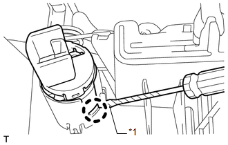
(b) Remove the power outlet socket assembly (w/o Climate Control Seat System).
|
(1) Using a screwdriver, detach the claw to remove the power point socket assembly. Text in Illustration
HINT: Tape the screwdriver tip before use. |
|
11. REMOVE POWER OUTLET SOCKET COVER
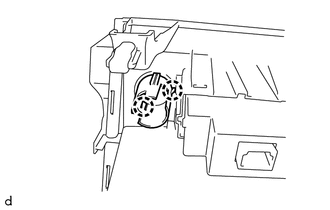
(a) Remove the power outlet socket cover (w/ Climate Control Seat System).
|
(1) Detach the 2 claws to remove the power outlet socket cover. |
|
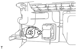
(b) Remove the power outlet socket cover (w/o Climate Control Seat System).
|
(1) Detach the 2 claws to remove the power outlet socket cover. |
|
 Components
COMPONENTS
ILLUSTRATION
ILLUSTRATION
...
 Installation
INSTALLATION
PROCEDURE
1. INSTALL POWER OUTLET SOCKET COVER
(a) Attach the 2 claws to install the socket cover.
2. INSTALL POWER OUTLET SOCKET ASSEMBLY
(a) Attach the claw to install the power ou ...
Other materials about Toyota 4Runner:
Security Horn Assembly
Components
COMPONENTS
ILLUSTRATION
Removal
REMOVAL
PROCEDURE
1. REMOVE AIR CLEANER CAP AND HOSE
2. REMOVE AIR CLEANER CASE SUB-ASSEMBLY
3. REMOVE SECURITY HORN ASSEMBLY
(a) Disconnect the connector.
...
Rear Brake Flexible Hose
Components
COMPONENTS
ILLUSTRATION
ILLUSTRATION
Removal
REMOVAL
CAUTION / NOTICE / HINT
HINT:
Use the same procedure for the RH and LH sides.
The procedure listed below is for the LH side.
PROCEDURE
1. REMOVE REAR WHEEL
2. ...

0.025