Toyota 4Runner: Removal
REMOVAL
PROCEDURE
1. REMOVE INSTRUMENT PANEL SUB-ASSEMBLY
(a) Remove the instrument panel sub-assembly (See page
.gif) ).
).
2. REMOVE NO. 2 INSTRUMENT PANEL WIRE
|
(a) Detach the clamp. |
|
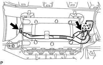
(b) Disconnect the 2 connectors and remove the wire.
NOTICE:
When handling the airbag connector, take care not to damage the airbag wire harness.
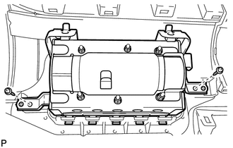
3. REMOVE INSTRUMENT PANEL PASSENGER AIRBAG ASSEMBLY
|
(a) Remove the 2 screws. |
|
|
(b) Detach the 5 hooks (A). Text in Illustration
|
|
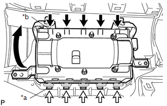
(c) Detach the 5 hooks (B) and remove the instrument panel passenger airbag.
 On-vehicle Inspection
ON-VEHICLE INSPECTION
PROCEDURE
1. CHECK INSTRUMENT PANEL PASSENGER AIRBAG ASSEMBLY (VEHICLE NOT INVOLVED IN
COLLISION)
(a) Perform a diagnostic system check (See page
).
(b) With the instrume ...
 Disposal
DISPOSAL
CAUTION / NOTICE / HINT
CAUTION:
Before performing pre-disposal deployment of any SRS part, review and closely
follow all applicable environmental and hazardous material regulations. Pre ...
Other materials about Toyota 4Runner:
Garage door opener
The garage door opener can be programmed to operate garage doors, gates,
entry doors, door locks, home lighting systems, security systems, and other
devices.
The garage door opener (HomeLink® Universal Transceiver) is manufactured
under license from Ho ...
Air Outlet Damper Control Servo Motor Circuit (B1443)
DESCRIPTION
The damper servo sub-assembly (mode damper servo) sends pulse signals to inform
the No. 1 air conditioning amplifier assembly of the damper position. The No. 1
air conditioning amplifier assembly activates the motor (normal or reverse) based
...

0.0252