Toyota 4Runner: Removal
REMOVAL
CAUTION / NOTICE / HINT
HINT:
- Use the same procedure for the RH and LH sides.
- The procedure listed below is for the LH side.
PROCEDURE
1. DISCONNECT CABLE FROM NEGATIVE BATTERY TERMINAL
CAUTION:
Wait at least 90 seconds after disconnecting the cable from the negative (-) battery terminal to disable the SRS system.
NOTICE:
When disconnecting the cable, some systems need to be initialized after the cable
is reconnected (See page .gif) ).
).
2. REMOVE REAR NO. 2 SEAT ASSEMBLY (w/ Rear No. 2 Seat)
(a) Remove the rear No. 2 seat assembly (See page
).
3. REMOVE REAR NO. 1 FLOOR STEP COVER (w/ Rear No. 2 Seat)
4. REMOVE QUARTER SCUFF PLATE LH (w/ Rear No. 2 Seat)
5. REMOVE REAR DOOR SCUFF PLATE LH
6. REMOVE REAR DOOR OPENING TRIM WEATHERSTRIP LH
7. REMOVE NO. 1 LUGGAGE COMPARTMENT TRIM COVER (w/o Deck Board)
8. REMOVE NO. 1 DECK BOARD SUB-ASSEMBLY (w/o Deck Board)
9. REMOVE NO. 2 LUGGAGE COMPARTMENT TRIM COVER (w/ Deck Board)
10. REMOVE NO. 2 DECK BOARD SUB-ASSEMBLY (w/ Deck Board)
11. REMOVE REAR NO. 2 FLOOR BOARD ASSEMBLY (w/ Deck Board)
12. REMOVE LUGGAGE COMPARTMENT SIDE COVER SUB-ASSEMBLY LH (w/ Deck Board)
13. REMOVE LUGGAGE COMPARTMENT SIDE COVER SUB-ASSEMBLY RH (w/ Deck Board)
14. REMOVE DECK BOARD ASSEMBLY (w/ Deck Board)
15. REMOVE INNER FLOOR SIDE RAIL SUB-ASSEMBLY (w/ Deck Board)
16. REMOVE REAR FLOOR MAT REAR SUPPORT PLATE
17. REMOVE REAR FLOOR CARPET ASSEMBLY (w/o Deck Board)
18. REMOVE REAR NO. 1 SEAT OUTER LAP BELT ANCHOR COVER
19. REMOVE NO. 1 LUGGAGE COMPARTMENT TRIM HOOK
20. REMOVE FRONT DECK SIDE TRIM COVER LH
21. REMOVE NO. 1 LUGGAGE COMPARTMENT TRIM COVER
22. REMOVE DECK TRIM SIDE PANEL ASSEMBLY LH
23. REMOVE REAR AIRBAG SENSOR LH
|
(a) Remove the nut and rear airbag sensor. |
|
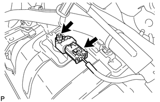
(b) Disconnect the connector.
 On-vehicle Inspection
ON-VEHICLE INSPECTION
CAUTION / NOTICE / HINT
HINT:
Use the same procedure for the RH and LH sides.
The procedure listed below is for the LH side.
PROCEDURE
1. CHECK REAR AIRBAG ...
 Installation
INSTALLATION
CAUTION / NOTICE / HINT
HINT:
Use the same procedure for the RH and LH sides.
The procedure listed below is for the LH side.
PROCEDURE
1. INSTALL REAR AIRBAG SENSOR ...
Other materials about Toyota 4Runner:
How To Proceed With Troubleshooting
CAUTION / NOTICE / HINT
HINT:
Use the following procedures to troubleshoot the key reminder warning
system.
*: Use the Techstream.
PROCEDURE
1.
VEHICLE BROUGHT TO WORKSHOP
NEXT
...
Voice Guidance does not Function
CAUTION / NOTICE / HINT
NOTICE:
After replacing the navigation receiver assembly of vehicles subscribed to pay-type
satellite radio broadcasts, registration of the XM radio ID is necessary.
PROCEDURE
1.
CHECK VOICE GUIDANCE
...

0.0116