Toyota 4Runner: Removal
REMOVAL
PROCEDURE
1. DISCONNECT CABLE FROM NEGATIVE BATTERY TERMINAL
NOTICE:
When disconnecting the cable some systems need to be initialized after the cable,
is reconnected (See page .gif) ).
).
2. REMOVE REAR NO. 1 FLOOR STEP COVER (w/ Rear No. 2 Seat)
3. REMOVE QUARTER SCUFF PLATE INNER RH (w/ Rear No. 2 Seat)
4. REMOVE REAR DOOR SCUFF PLATE RH
5. REMOVE REAR DOOR OPENING TRIM WEATHERSTRIP RH
6. REMOVE OUTER LAP BELT ANCHOR COVER
7. REMOVE NO. 1 LUGGAGE COMPARTMENT TRIM COVER (w/o Deck Board)
8. REMOVE NO. 1 DECK BOARD SUB-ASSEMBLY (w/o Deck Board)
9. REMOVE NO. 2 LUGGAGE COMPARTMENT TRIM COVER (w/ Deck Board, w/o Rear No. 2 Seat)
10. REMOVE NO. 2 DECK BOARD SUB-ASSEMBLY (w/ Deck Board)
11. REMOVE REAR NO. 2 FLOOR BOARD ASSEMBLY (w/ Deck Board)
12. REMOVE LUGGAGE COMPARTMENT SIDE COVER SUB-ASSEMBLY LH (w/ Deck Board)
13. REMOVE LUGGAGE COMPARTMENT SIDE COVER SUB-ASSEMBLY RH (w/ Deck Board)
14. REMOVE DECK BOARD ASSEMBLY (w/ Deck Board)
15. REMOVE INNER FLOOR SIDE RAIL SUB-ASSEMBLY (w/ Deck Board)
16. REMOVE REAR FLOOR MAT REAR SUPPORT PLATE
17. REMOVE REAR FLOOR CARPET ASSEMBLY (w/o Deck Board)
18. REMOVE REAR NO. 1 SEAT OUTER LAP BELT ANCHOR COVER
19. REMOVE NO. 1 LUGGAGE COMPARTMENT TRIM HOOK
20. REMOVE FRONT DECK SIDE TRIM COVER RH
21. REMOVE NO. 1 LUGGAGE COMPARTMENT TRIM COVER
22. REMOVE DECK TRIM SIDE PANEL ASSEMBLY RH
23. REMOVE STEREO COMPONENT AMPLIFIER ASSEMBLY
|
(a) Disconnect the 4 connectors. |
|
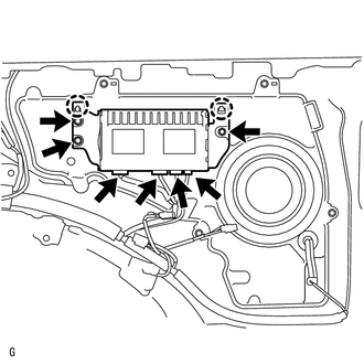
(b) Remove the 3 bolts.
(c) Detach the 2 claws and remove the stereo component amplifier.
 Components
COMPONENTS
ILLUSTRATION
ILLUSTRATION
ILLUSTRATION
ILLUSTRATION
ILLUSTRATION
...
 Installation
INSTALLATION
PROCEDURE
1. INSTALL STEREO COMPONENT AMPLIFIER ASSEMBLY
(a) Insert the stereo component amplifier to attach the 2 claws.
(b) Install the amplifier with the 3 bolts.
Torque:
2.5 NÂ ...
Other materials about Toyota 4Runner:
Inspection
INSPECTION
PROCEDURE
1. INSPECT BRAKE VACUUM CHECK VALVE ASSEMBLY
(a) Check that there is ventilation from the booster to the engine and
no ventilation from the engine to the booster.
Text in Illustration
*a
...
Back Sonar Sensor LH Circuit
DESCRIPTION
The ultrasonic sensor sends and receives ultrasonic waves. Based on the received
wave, the sensor calculates the approximate distance between the vehicle and the
obstacle, and sends the distance value as a signal to the clearance warning ECU
...

0.0131