Toyota 4Runner: Back Sonar Sensor LH Circuit
DESCRIPTION
The ultrasonic sensor sends and receives ultrasonic waves. Based on the received wave, the sensor calculates the approximate distance between the vehicle and the obstacle, and sends the distance value as a signal to the clearance warning ECU assembly.
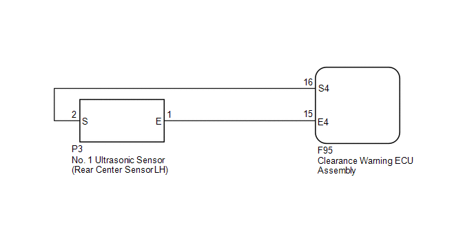
WIRING DIAGRAM
PROCEDURE
|
1. |
INSPECT NO. 1 ULTRASONIC SENSOR (REAR CENTER SENSOR LH) |
(a) Remove the No. 1 ultrasonic sensor (rear center sensor LH) (See page
.gif) ).
).
(b) Inspect the No. 1 ultrasonic sensor (rear center sensor LH) (See page
).
| NG | .gif) |
REPLACE NO. 1 ULTRASONIC SENSOR (REAR CENTER SENSOR LH) |
|
.gif)
|
2. |
CHECK HARNESS AND CONNECTOR (REAR CENTER SENSOR LH - CLEARANCE WARNING ECU ASSEMBLY) |
(a) Disconnect the P3 No. 1 ultrasonic sensor (rear center sensor LH) connector.
(b) Disconnect the F95 clearance warning ECU assembly connector.
(c) Measure the resistance according to the value(s) in the table below.
Standard Resistance:
|
Tester Connection |
Condition |
Specified Condition |
|---|---|---|
|
P3-1 (E) - F95-15 (E4) |
Always |
Below 1 Ω |
|
P3-2 (S) - F95-16 (S4) |
Always |
Below 1 Ω |
|
P3-1 (E) - Body ground |
Always |
10 kΩ or higher |
|
P3-2 (S) - Body ground |
Always |
10 kΩ or higher |
| OK | |
PROCEED TO NEXT SUSPECTED AREA SHOWN IN PROBLEM SYMPTOMS TABLE |
| NG | |
REPAIR OR REPLACE HARNESS OR CONNECTOR |
 Taillight Relay Circuit
DESCRIPTION
This is the power source circuit of the clearance warning ECU assembly.
WIRING DIAGRAM
CAUTION / NOTICE / HINT
NOTICE:
Inspect the fuses for circuits related to this system before p ...
 Back Sonar Sensor RH Circuit
DESCRIPTION
The ultrasonic sensor sends and receives ultrasonic waves. Based on the received
wave, the sensor calculates the approximate distance between the vehicle and the
obstacle, and sends t ...
Other materials about Toyota 4Runner:
Inspection
INSPECTION
PROCEDURE
1. INSPECT DOOR CONTROL SWITCH ASSEMBLY
(a) Measure the resistance according to the value(s) in the table below.
Standard Resistance:
Tester Connection
Condition
Speci ...
Installation
INSTALLATION
CAUTION / NOTICE / HINT
CAUTION:
Wear protective gloves. Sharp areas on the parts may injure your hands.
HINT:
The procedure listed below is for the RH side.
PROCEDURE
1. INSTALL FRONT SEAT ASSEMBLY
(a) Place the front seat assembly in the ...

0.0221