Toyota 4Runner: Removal
REMOVAL
PROCEDURE
1. DISCONNECT CABLE FROM NEGATIVE BATTERY TERMINAL
CAUTION:
Wait at least 90 seconds after disconnecting the cable from the negative (-) battery terminal to disable the SRS system.
NOTICE:
When disconnecting the cable, some systems need to be initialized after the cable
is reconnected (See page .gif) ).
).
2. REMOVE NO. 1 INSTRUMENT CLUSTER FINISH PANEL GARNISH
3. REMOVE NO. 2 INSTRUMENT CLUSTER FINISH PANEL GARNISH
4. REMOVE HEATER CONTROL ASSEMBLY
5. REMOVE SHIFT LEVER KNOB SUB-ASSEMBLY
6. REMOVE SHIFT LEVER KNOB SUB-ASSEMBLY (for VF2A)
7. REMOVE UPPER CONSOLE PANEL SUB-ASSEMBLY
8. REMOVE NO. 2 CONSOLE BOX RETAINER
9. REMOVE LOWER CENTER INSTRUMENT CLUSTER FINISH PANEL SUB-ASSEMBLY (w/ Climate Control Seat System)
10. REMOVE LOWER CENTER INSTRUMENT CLUSTER FINISH PANEL SUB-ASSEMBLY (w/o Climate Control Seat System)
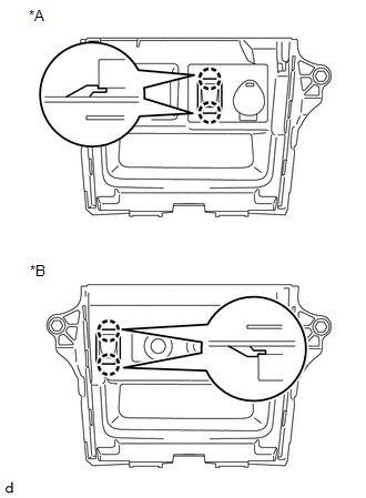
11. REMOVE NO. 1 STEREO JACK ADAPTER ASSEMBLY
|
(a) Detach the 2 claws to remove the No. 1 stereo jack adapter assembly. Text in Illustration
|
|
 Components
COMPONENTS
ILLUSTRATION
ILLUSTRATION
...
 Installation
INSTALLATION
PROCEDURE
1. INSTALL NO. 1 STEREO JACK ADAPTER ASSEMBLY
(a) Attach the 2 claws to install the No. 1 stereo jack adapter assembly.
2. INSTALL LOWER CENTER INSTRUMENT CLUSTER FINISH PAN ...
Other materials about Toyota 4Runner:
Adjustment
ADJUSTMENT
PROCEDURE
1. CHECK BRAKE PEDAL HEIGHT
(a) Check the brake pedal height.
Pedal height from Floor panel:
158.8 to 168.8 mm (6.25 to 6.46 in.)
Text in Illustration
*a
Pedal Height
...
LIN Communication Master Malfunction (B2287,B278C)
DESCRIPTION
DTC B2287 is stored when there is an open or short circuit or an ECU
communication malfunction between the power management control ECU and certification
ECU.
DTC B278C is stored when LIN communication between the certification ...

0.0104