Toyota 4Runner: Removal
REMOVAL
CAUTION / NOTICE / HINT
NOTICE:
Make sure to release the vacuum from the brake booster before removing the master cylinder from the brake booster.
PROCEDURE
1. DRAIN BRAKE FLUID
NOTICE:
Wash off brake fluid immediately if it comes in contact with any painted surface.
2. REMOVE BRAKE MASTER CYLINDER SUB-ASSEMBLY
(a) Remove the brake master cylinder sub-assembly (See page
.gif) ).
).
3. REMOVE BRAKE PEDAL RETURN SPRING
4. REMOVE PUSH ROD PIN
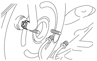
5. DISCONNECT BRAKE MASTER CYLINDER PUSH ROD CLEVIS
(a) Loosen the brake master cylinder push rod clevis lock nut.
(b) Disconnect the brake master cylinder push rod clevis.
6. DISCONNECT VACUUM HOSE
|
(a) Slide the clip and disconnect the vacuum hose. |
|
7. REMOVE BRAKE VACUUM CHECK VALVE ASSEMBLY
(a) Remove the vacuum check valve assembly from the brake booster assembly.
8. REMOVE CHECK VALVE GROMMET
(a) Remove the check valve grommet from the brake booster assembly.
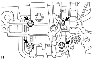
9. REMOVE BRAKE BOOSTER ASSEMBLY
|
(a) Remove the 4 nuts and brake booster assembly from the body. NOTICE: Do not damage the brake lines. |
|
10. REMOVE BRAKE BOOSTER GASKET
(a) Remove the brake booster gasket from the brake booster assembly.
11. REMOVE BRAKE MASTER CYLINDER PUSH ROD CLEVIS
(a) Loosen the lock nut and remove the brake master cylinder push rod clevis and lock nut from the brake booster assembly.
 On-vehicle Inspection
ON-VEHICLE INSPECTION
PROCEDURE
1. INSPECT BRAKE BOOSTER ASSEMBLY
(a) Airtightness check
(1) Start the engine and stop it after 1 or 2 minutes. Slowly depress
the brake pedal severa ...
 Inspection
INSPECTION
PROCEDURE
1. INSPECT BRAKE VACUUM CHECK VALVE ASSEMBLY
(a) Check that there is ventilation from the booster to the engine and
no ventilation from the engine to the booster ...
Other materials about Toyota 4Runner:
System Description
SYSTEM DESCRIPTION
1. SEAT BELT WARNING SYSTEM DESCRIPTION
If a seat belt is not fastened, this system flashes the seat belt warning light
or sounds the seat belt warning buzzer as a reminder.
(a) Driver side seat belt warning light:
The seat belt warnin ...
Dtc Check / Clear
DTC CHECK / CLEAR
1. CHECK DTC (Using SST Check Wire)
(a) Check for DTCs (present trouble code).
(1) Turn the ignition switch to ON and wait for approximately 60 seconds.
(2) Using SST, connect terminals 13 (TC) and 4 (CG) of the DLC3.
SST: 09843-18040
N ...

0.0125