Toyota 4Runner: Removal
REMOVAL
PROCEDURE
1. DISCONNECT CABLE FROM NEGATIVE BATTERY TERMINAL
CAUTION:
Wait at least 90 seconds after disconnecting the cable from the negative (-) battery terminal to disable the SRS system.
NOTICE:
When disconnecting the cable, some systems need to be initialized after the cable
is reconnected (See page .gif) ).
).
2. REMOVE REAR CONSOLE BOX ASSEMBLY
(a) Remove the rear console box assembly (See page
).
3. REMOVE NO. 1 PARKING BRAKE CABLE ASSEMBLY
(a) Remove the No. 1 parking brake cable assembly (See page
).
4. REMOVE FUEL TANK SUB-ASSEMBLY
(a) Remove the fuel tank sub-assembly (See page
).
5. REMOVE NO. 2 PARKING BRAKE SHOE ASSEMBLY WITH PARKING BRAKE SHOE LEVER
HINT:
Refer to the procedures up to "Remove No. 2 Parking Brake Shoe Assembly with
Parking Brake Shoe Lever" (See page ).
6. REMOVE NO. 2 PARKING BRAKE CABLE ASSEMBLY
|
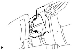
(a) Remove the 2 bolts and disconnect the No. 2 parking brake cable assembly from the backing plate. |
|
|
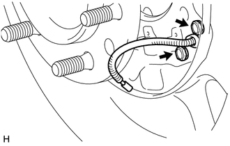
(b) Remove the No. 1 parking brake cable heat insulator. |
|
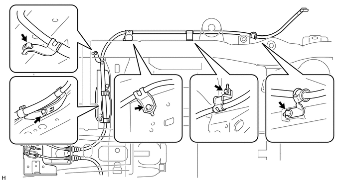
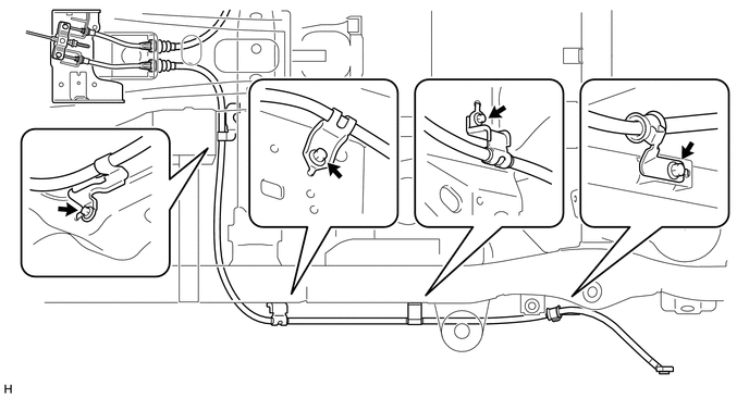
(c) Remove the 5 bolts from the No. 2 parking brake cable assembly.
|
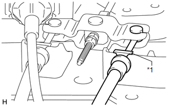
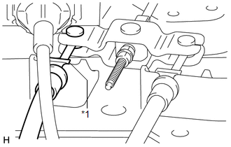
(d) Remove the clip and disconnect the No. 2 parking brake cable assembly from the parking brake equalizer. Text in Illustration
|
|
|
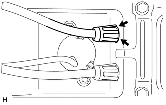
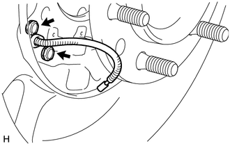
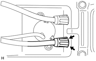
(e) Pinch the claws of the No. 2 parking brake cable and push the cable outside of the vehicle slightly. |
|
7. REMOVE NO. 3 PARKING BRAKE CABLE ASSEMBLY
|
(a) Remove the 2 bolts and disconnect the No. 3 parking brake cable assembly from the backing plate. |
|
(b) Remove the 4 bolts from the No. 3 parking brake cable assembly.
|
(c) Remove the clip and disconnect the parking brake cable assembly No. 3 from the parking brake equalizer. Text in Illustration
|
|
|
(d) Pinch the claws of the No. 3 parking brake cable and push the cable outside of the vehicle slightly. |
|
 Installation
INSTALLATION
PROCEDURE
1. INSTALL NO. 2 PARKING BRAKE CABLE ASSEMBLY
(a) Attach the claws of the No. 2 parking brake cable.
(b) Install the No. 2 parking brake cable assembly to the parking brake ...

Other materials about Toyota 4Runner:
Inspection
INSPECTION
PROCEDURE
1. INSPECT TRANSFER INPUT SHAFT
(a) Using a micrometer, measure the diameter of the input shaft journal.
Minimum diameter:
47.59 mm (1.88 in.)
If the diameter is less than the minimum, replace the input shaft.
(b) Usin ...
Reassembly
REASSEMBLY
CAUTION / NOTICE / HINT
HINT:
Use the same procedure for both the RH and LH sides.
The procedure listed below is for the LH side.
PROCEDURE
1. INSTALL NO. 3 OUTSIDE MOULDING RETAINER
2. INSTALL REAR DOOR OUTSIDE MOULDING L ...

0.0285