Toyota 4Runner: Removal
REMOVAL
PROCEDURE
1. REMOVE PARK/NEUTRAL POSITION SWITCH ASSEMBLY
(a) Disconnect the switch connector.
|
(b) Using a screwdriver, bend the tabs of the lock washer. |
|
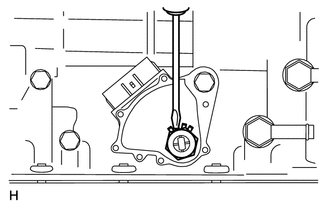
|
(c) Remove the lock nut and lock washer. |
|
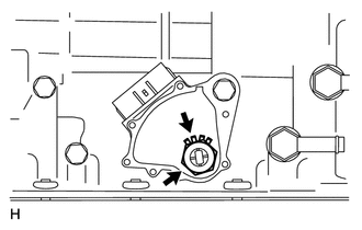
|
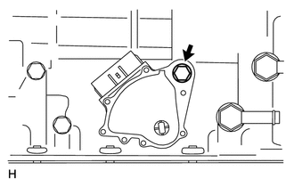
(d) Remove the bolt and switch. HINT: Make sure that the manual valve lever shaft has not been rotated prior to installing the park/neutral position switch assembly as the detent spring may become detached from the manual valve lever shaft. |
|
 On-vehicle Inspection
ON-VEHICLE INSPECTION
PROCEDURE
1. INSPECT PARK/NEUTRAL POSITION SWITCH ASSEMBLY
(a) Apply the parking brake and turn the ignition switch on (IG).
(b) Depress the brake pedal and check that the en ...
 Inspection
INSPECTION
PROCEDURE
1. INSPECT PARK/NEUTRAL POSITION SWITCH ASSEMBLY
(a) Measure the resistance according to the value(s) in the table below.
Standard Resistance:
Tester Connection ...
Other materials about Toyota 4Runner:
Back Sonar Sensor LH Circuit
DESCRIPTION
The ultrasonic sensor sends and receives ultrasonic waves. Based on the received
wave, the sensor calculates the approximate distance between the vehicle and the
obstacle, and sends the distance value as a signal to the clearance warning ECU
...
Dtc Check / Clear
DTC CHECK / CLEAR
1. CHECK DTC
(a) Connect the Techstream to the DLC3.
(b) Turn the engine switch on (IG).
(c) Turn the Techstream on.
(d) Enter the following menus: Body Electrical / Smart Key / Trouble Codes.
(e) Check for DTCs.
2. CLEAR DTC
(a) Conn ...

0.0109