Toyota 4Runner: Reverse Signal Circuit
DESCRIPTION
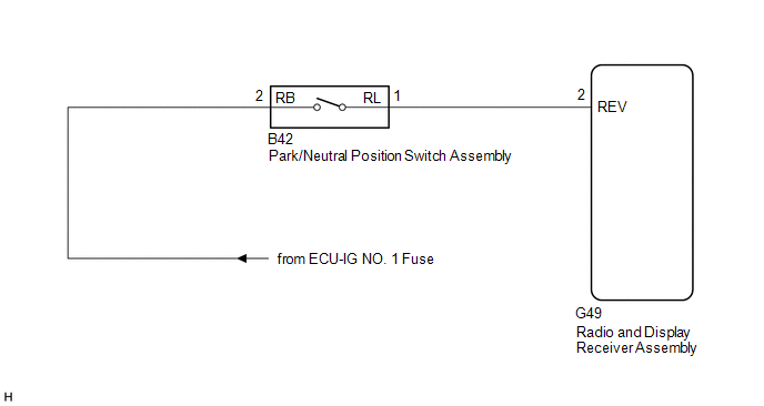
The radio and display receiver assembly receives a reverse signal from the park/neutral position switch assembly.
WIRING DIAGRAM
PROCEDURE
|
1. |
CHECK HARNESS AND CONNECTOR (REVERSE SIGNAL) |
(a) Disconnect the G49 radio and display receiver assembly connector.
(b) Measure the voltage according to the value(s) in the table below.
Standard Voltage:
|
Tester Connection |
Switch Condition |
Specified Condition |
|---|---|---|
|
G49-2 (REV) - Body ground |
Ignition switch ON Shift lever in R |
11 to 14 V |
|
G49-2 (REV) - Body ground |
Ignition switch ON Shift lever in any position other than R |
Below 1 V |
| OK | .gif) |
PROCEED TO NEXT SUSPECTED AREA SHOWN IN PROBLEM SYMPTOMS TABLE |
|
.gif)
|
2. |
CHECK HARNESS AND CONNECTOR (RADIO AND DISPLAY RECEIVER ASSEMBLY - PARK/NEUTRAL POSITION SWITCH ASSEMBLY) |
(a) Disconnect the G49 radio and display receiver assembly connector.
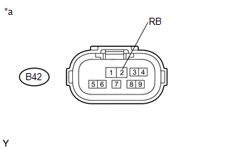
(b) Disconnect the B42 park/neutral position switch assembly connector.
(c) Measure the resistance according to the value(s) in the table below.
Standard Resistance:
|
Tester Connection |
Condition |
Specified Condition |
|---|---|---|
|
G49-2 (REV) - B42-1 (RL) |
Always |
Below 1 Ω |
|
G49-2 (REV) - Body ground |
Always |
10 kΩ or higher |
| NG | |
REPAIR OR REPLACE HARNESS OR CONNECTOR |
|
|
3. |
CHECK HARNESS AND CONNECTOR (PARK/NEUTRAL POSITION SWITCH ASSEMBLY - BATTERY) |
(a) Disconnect the B42 park/neutral position switch assembly connector.
|
(b) Measure the voltage according to the value(s) in the table below. Standard Voltage:
|
|
(c) Proceed to the next step based on the check result.
|
Result |
Proceed to |
|---|---|
|
NG |
A |
|
OK (for A750E) |
B |
|
OK (for A750F) |
C |
| A | |
REPAIR OR REPLACE HARNESS OR CONNECTOR |
| B | |
REPLACE PARK/NEUTRAL POSITION SWITCH ASSEMBLY |
| C | |
REPLACE PARK/NEUTRAL POSITION SWITCH ASSEMBLY |
 Data Signal Circuit between Radio Receiver and Extension Module
DESCRIPTION
The stereo component tuner assembly sends the sound data signal or image data
signal from a device to the radio and display receiver assembly via this circuit.
WIRING DIAGRAM
PROCED ...
 Microphone Circuit between Microphone and Radio Receiver
DESCRIPTION
The radio and display receiver assembly and map light assembly (telephone
microphone assembly) are connected to each other using the microphone connection
detection signal ...
Other materials about Toyota 4Runner:
Meter Illumination does not Dim at Night
DESCRIPTION
If the dimmer switch is turned to TAIL, HEAD or AUTO, the main body ECU sends
a TAIL relay signal, panel light illumination signal, panel relay signal and TAIL
cancel OFF signal to the combination meter. Then the meter and accessory meter beco ...
System Diagram
SYSTEM DIAGRAM
Communication Table
Transmitter
Receiver
Signal
Communication Line
Air conditioning amplifier assembly
ECM
A/C idle up request signal
CAN
...

0.0068