Toyota 4Runner: Removal
REMOVAL
PROCEDURE
1. REMOVE DOOR SCUFF PLATE ASSEMBLY LH
.gif)
2. REMOVE COWL SIDE TRIM BOARD LH
3. REMOVE NO. 2 SWITCH HOLE BASE
4. REMOVE NO. 1 INSTRUMENT CLUSTER FINISH PANEL GARNISH
5. REMOVE LOWER INSTRUMENT PANEL FINISH PANEL SUB-ASSEMBLY
6. REMOVE TURN SIGNAL FLASHER ASSEMBLY
|
(a) Disconnect the connector. |
|
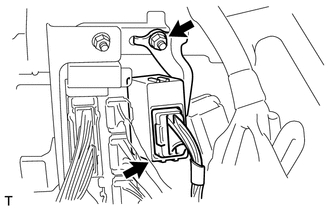
(b) Remove the nut and flasher.
 On-vehicle Inspection
ON-VEHICLE INSPECTION
PROCEDURE
1. CHECK TURN SIGNAL FLASHER ASSEMBLY
(a) Measure the resistance according to the value(s) in the table below.
Standard Resistance:
...
 Installation
INSTALLATION
PROCEDURE
1. INSTALL TURN SIGNAL FLASHER ASSEMBLY
(a) Install the turn signal flasher assembly with the nut.
Torque:
5.5 N·m {56 kgf·cm, 49 in·lbf}
(b) Connect the connector.
2 ...
Other materials about Toyota 4Runner:
If the electronic key does not operate properly (vehicles with a smart key
system)
If communication between the electronic key and vehicle is interrupted
or the electronic key cannot be used because the battery is depleted, the smart
key system and wireless remote control cannot be used. In such cases, the doors
can be opened and ...
1-2 Shift (1-2 Shift Valve) (P0781)
DESCRIPTION
The 1-2 shift valve performs shifting to 1st gear and other gears.
DTC Code
DTC Detection Condition
Trouble Area
P0781
Gear required by the ECM does not match the actual gear when drivi ...

0.2907