Toyota 4Runner: Rocker Panel Moulding
Components
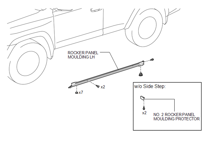
COMPONENTS
ILLUSTRATION
Removal
REMOVAL
CAUTION / NOTICE / HINT
HINT:
- Use the same procedure for both the RH and LH sides.
- The procedure listed below is for the LH side.
PROCEDURE
1. REMOVE SIDE STEP ASSEMBLY LH (w/ Side Step)
(See page .gif) )
)
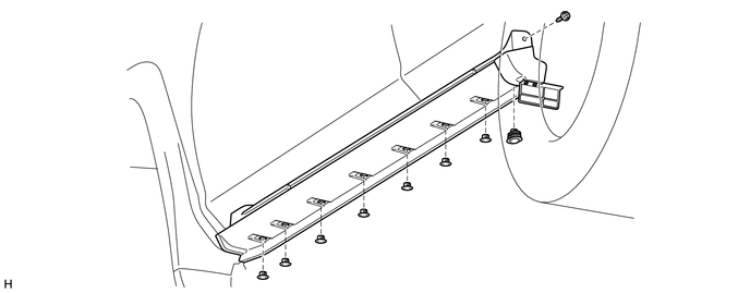
2. REMOVE ROCKER PANEL MOULDING LH
(a) Remove the 7 retainers, clip and screw.
(b) Put protective tape around the rocker panel moulding LH.
(c) Remove the 2 screws.
(d) Detach the 7 clips to remove the rocker panel moulding LH.
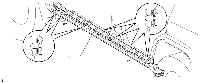 Text in Illustration
|
*1 |
Protective Tape |
- |
- |
3. REMOVE NO. 2 ROCKER PANEL MOULDING PROTECTOR (w/o Side Step)
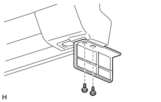
(a) Remove the 2 screws and No. 2 rocker panel moulding protector.
Installation
INSTALLATION
CAUTION / NOTICE / HINT
HINT:
- Use the same procedure for both the RH and LH sides.
- The procedure listed below is for the LH side.
PROCEDURE
1. INSTALL NO. 2 ROCKER PANEL MOULDING PROTECTOR (w/o Side Step)
(a) Install the No. 2 rocker panel moulding protector with the 2 screws.
2. INSTALL ROCKER PANEL MOULDING LH
(a) Attach the 7 clips to install the rocker panel moulding LH.
(b) Install the 3 screws.
(c) Attach the 7 retainers and clip.
3. INSTALL SIDE STEP ASSEMBLY LH (w/ Side Step)
(See page .gif) )
)
 Installation
INSTALLATION
CAUTION / NOTICE / HINT
HINT:
A bolt without a torque specification is shown in the standard bolt chart (See
page ).
PROCEDURE
1. INSTALL REAR NO. 2 SPOILER CLIP
HINT:
Use the s ...
 Rocker Panel Moulding(w/ Intuitive Parking Assist System)
Components
COMPONENTS
ILLUSTRATION
Installation
INSTALLATION
CAUTION / NOTICE / HINT
HINT:
Use the same procedure for both the RH and LH sides.
The procedure listed below is f ...
Other materials about Toyota 4Runner:
Installation
INSTALLATION
PROCEDURE
1. INSTALL BACK DOOR POWER WINDOW REGULATOR MOTOR ASSEMBLY
(a) Using a T25 "TORX" socket wrench, install the back power window regulator
motor assembly with the 3 screws.
HINT:
Tighten the sc ...
Trouble in Passenger Airbag ON/OFF Indicator
DESCRIPTION
The occupant classification system detects the front passenger seat condition.
The system then informs the passenger of the front passenger airbag assembly and
front passenger side knee airbag status (activated/not activated) with the passenge ...

0.0078