Toyota 4Runner: Room Temperature Sensor
Components
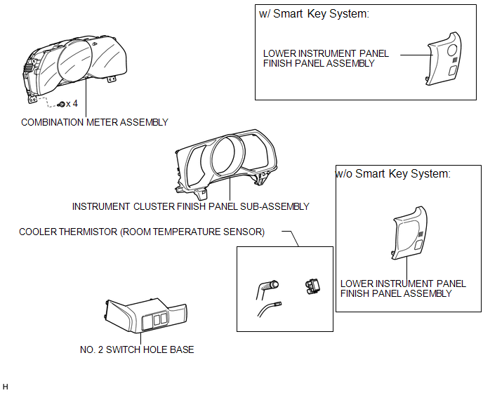
COMPONENTS
ILLUSTRATION
Removal
REMOVAL
PROCEDURE
1. DISCONNECT CABLE FROM NEGATIVE BATTERY TERMINAL
NOTICE:
When disconnecting the cable, some systems need to be initialized after the cable
is reconnected (See page .gif) ).
).
2. REMOVE NO. 2 SWITCH HOLE BASE
3. REMOVE LOWER INSTRUMENT PANEL FINISH PANEL ASSEMBLY
4. REMOVE INSTRUMENT CLUSTER FINISH PANEL SUB-ASSEMBLY
5. REMOVE COMBINATION METER ASSEMBLY
6. REMOVE COOLER THERMISTOR (ROOM TEMPERATURE SENSOR)
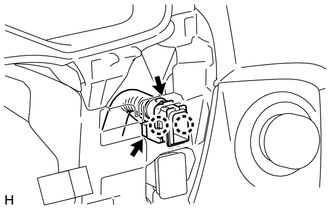
(a) Disconnect the connector and hose.
(b) Detach the 2 claws and remove the cooler thermistor.
Inspection
INSPECTION
PROCEDURE
1. INSPECT COOLER THERMISTOR (ROOM TEMPERATURE SENSOR)
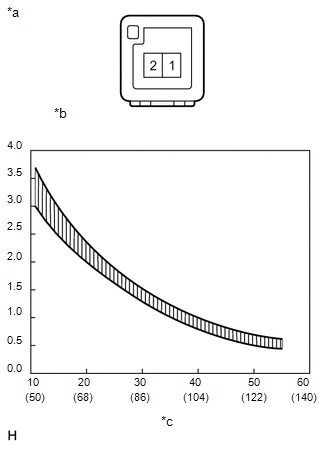
(a) Measure the resistance according to the value(s) in the table below.
Standard Resistance:
|
Tester Connection |
Condition |
Specified Condition |
|---|---|---|
|
1 - 2 |
10°C (50°F) |
3.00 to 3.73 kΩ |
|
15°C (59°F) |
2.45 to 2.88 kΩ |
|
|
20°C (68°F) |
1.95 to 2.30 kΩ |
|
|
25°C (77°F) |
1.60 to 1.80 kΩ |
|
|
30°C (86°F) |
1.28 to 1.47 kΩ |
|
|
35°C (95°F) |
1.00 to 1.22 kΩ |
|
|
40°C (104°F) |
0.80 to 1.00 kΩ |
|
|
45°C (113°F) |
0.65 to 0.85 kΩ |
|
|
50°C (122°F) |
0.50 to 0.70 kΩ |
|
|
55°C (131°F) |
0.44 to 0.60 kΩ |
|
|
60°C (140°F) |
0.36 to 0.50 kΩ |
HINT:
As the temperature increases, the resistance decreases (refer to the graph).
NOTICE:
- Touching the sensor even slightly may change the resistance value. Hold the connector of the sensor.
- When measuring the resistance, make sure the sensor temperature is the same as the ambient temperature.
If the result is not as specified, replace the cooler thermistor (room temperature sensor).
Text in Illustration|
*a |
Component without harness connected (Cooler Thermistor (Room Temperature Sensor)) |
|
*b |
Resistance (kΩ) |
|
*c |
Temperature (°C(°F)) |
Installation
INSTALLATION
PROCEDURE
1. INSTALL COOLER THERMISTOR (ROOM TEMPERATURE SENSOR)
(a) Attach the 2 claws to install the cooler thermistor.
(b) Connect the connector and hose.
2. INSTALL COMBINATION METER ASSEMBLY
.gif)
3. INSTALL INSTRUMENT CLUSTER FINISH PANEL SUB-ASSEMBLY
4. INSTALL LOWER INSTRUMENT PANEL FINISH PANEL ASSEMBLY
5. INSTALL NO. 2 SWITCH HOLE BASE
6. CONNECT CABLE TO NEGATIVE BATTERY TERMINAL
NOTICE:
When disconnecting the cable, some systems need to be initialized after the cable
is reconnected (See page ).
 Relay(w/ Ptc Heater)
On-vehicle Inspection
ON-VEHICLE INSPECTION
PROCEDURE
1. REMOVE PTC HEATER RELAY (PTC NO. 1, PTC NO. 1, PTC NO. 3)
(a) Remove the 3 PTC heater relays from the engine room relay block. ...
 Solar Sensor
Components
COMPONENTS
ILLUSTRATION
Inspection
INSPECTION
PROCEDURE
1. INSPECT AUTOMATIC LIGHT CONTROL SENSOR (SOLAR SENSOR)
(a) Connect the positive (+) lead of the battery to ...
Other materials about Toyota 4Runner:
Inspection
INSPECTION
PROCEDURE
1. INSPECT REAR NO. 1 SEAT OUTER BELT ASSEMBLY RH
NOTICE:
Do not disassemble the retractor.
(a) When the inclination of the retractor is 15° or less, check that the belt
can be pulled from the retractor. When the inclination of t ...
ABS Warning Light does not Come ON
DESCRIPTION
Refer to ABS Warning Light Remains ON (See page
).
WIRING DIAGRAM
Refer to ABS Warning Light Remains ON (See page
).
CAUTION / NOTICE / HINT
NOTICE:
When replacing the master cylinder solenoid, perform calibration (See page
).
PROCEDUR ...

0.0142