Toyota 4Runner: Solar Sensor
Components
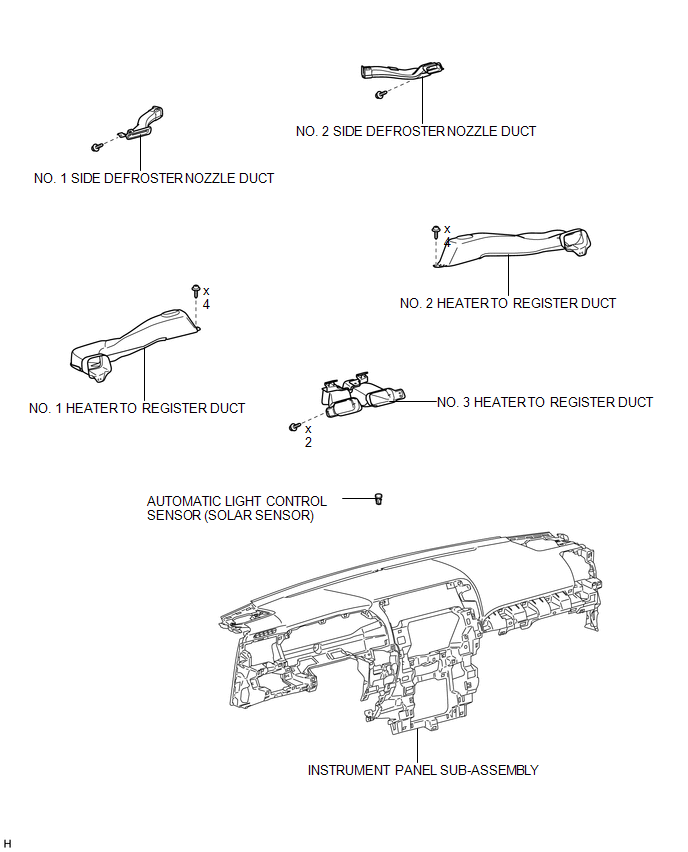
COMPONENTS
ILLUSTRATION
Inspection
INSPECTION
PROCEDURE
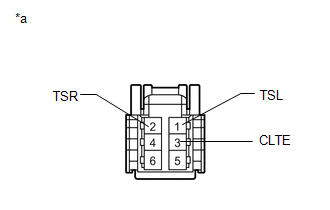
1. INSPECT AUTOMATIC LIGHT CONTROL SENSOR (SOLAR SENSOR)
|
(a) Connect the positive (+) lead of the battery to terminal 6 and the negative (-) lead to terminal 3, and then measure the voltage according to the value(s) in the table below. Standard Voltage:
HINT:
NOTICE: The connection procedure for using a digital tester, such as a TOYOTA electrical tester, is shown above. If the result is not as specified, replace the automatic light control sensor. Text in Illustration
|
|
Removal
REMOVAL
PROCEDURE
1. REMOVE INSTRUMENT PANEL SUB-ASSEMBLY
(a) Remove the instrument panel sub-assembly (See page
.gif) ).
).
2. REMOVE NO. 1 HEATER TO REGISTER DUCT
3. REMOVE NO. 2 HEATER TO REGISTER DUCT
4. REMOVE NO. 1 SIDE DEFROSTER NOZZLE DUCT
5. REMOVE NO. 2 SIDE DEFROSTER NOZZLE DUCT
6. REMOVE NO. 3 HEATER TO REGISTER DUCT
7. REMOVE AUTOMATIC LIGHT CONTROL SENSOR (SOLAR SENSOR)
.png)
(a) Disconnect the connector.
(b) Detach the 2 claws and remove the sensor.
Installation
INSTALLATION
PROCEDURE
1. INSTALL AUTOMATIC LIGHT CONTROL SENSOR (SOLAR SENSOR)
.png)
(a) Attach the 2 claws to install the sensor.
(b) Connect the connector.
2. INSTALL NO. 3 HEATER TO REGISTER DUCT
.gif)
3. INSTALL NO. 2 SIDE DEFROSTER NOZZLE DUCT
4. INSTALL NO. 1 SIDE DEFROSTER NOZZLE DUCT
5. INSTALL NO. 2 HEATER TO REGISTER DUCT
6. INSTALL NO. 1 HEATER TO REGISTER DUCT
7. INSTALL INSTRUMENT PANEL SUB-ASSEMBLY
(a) Install the instrument panel sub-assembly (See page
).
 Room Temperature Sensor
Components
COMPONENTS
ILLUSTRATION
Removal
REMOVAL
PROCEDURE
1. DISCONNECT CABLE FROM NEGATIVE BATTERY TERMINAL
NOTICE:
When disconnecting the cable, some systems need to be initialized ...

Other materials about Toyota 4Runner:
Poor Sound Quality in All Modes (Low Volume)
PROCEDURE
1.
CHECK AUDIO SETTINGS
(a) Set "Treble", "Mid" and "Bass" to the initial values and check that sound
is normal.
OK:
Malfunction disappears.
HINT:
Sound quality adjustment measure ...
Problem Symptoms Table
PROBLEM SYMPTOMS TABLE
HINT:
Use the table below to help determine the cause of problem symptoms.
If multiple suspected areas are listed, the potential causes of the symptoms
are listed in order of probability in the "Suspected Area" ...

0.0064