Toyota 4Runner: Sliding Roof ECU Power Source Circuit
DESCRIPTION
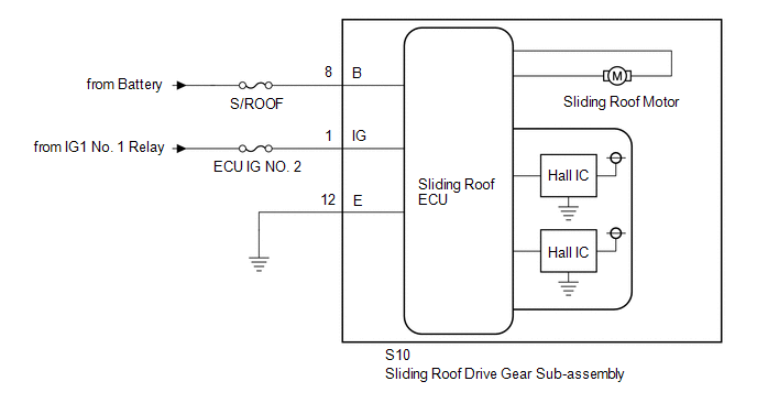
If the sliding function and tilt function do not operate, there may be a malfunction in the sliding roof drive gear sub-assembly power source circuit.
WIRING DIAGRAM
CAUTION / NOTICE / HINT
NOTICE:
- When the sliding roof drive gear sub-assembly (sliding roof ECU) is
removed and reinstalled or replaced, the sliding roof drive gear sub-assembly
(sliding roof ECU) must be initialized (See page
.gif) ).
). - Inspect the fuses for circuits related to this system before performing the following inspection procedure.
PROCEDURE
|
1. |
CHECK HARNESS AND CONNECTOR (SLIDING ROOF DRIVE GEAR SUB-ASSEMBLY (SLIDING ROOF ECU) - BATTERY AND BODY GROUND) |
|
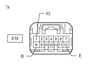
*a |
Front view of wire harness connector (to Sliding Roof Drive Gear Sub-assembly (Sliding Roof ECU)) |
(a) Disconnect the S10 sliding roof drive gear sub-assembly (sliding roof ECU) connector.
(b) Measure the resistance and voltage according to the value(s) in the table below.
Standard Voltage:
|
Tester Connection |
Switch Condition |
Specified Condition |
|---|---|---|
|
S10-8 (B) - Body ground |
Always |
11 to 14 V |
|
S10-1 (IG) - Body ground |
Ignition switch off |
Below 1 V |
|
S10-1 (IG) - Body ground |
Ignition switch ON |
11 to 14 V |
Standard Resistance
|
Tester Connection |
Condition |
Specified Condition |
|---|---|---|
|
S10-12 (E) - Body ground |
Always |
Below 1 Ω |
| OK | .gif) |
REPLACE SLIDING ROOF DRIVE GEAR SUB-ASSEMBLY (SLIDING ROOF ECU) |
| NG | |
REPAIR OR REPLACE HARNESS OR CONNECTOR |
 Sliding Roof Control Switch Circuit
DESCRIPTION
The sliding roof drive gear sub-assembly (sliding roof ECU) receives sliding
roof switch signals and drives its built-in motor.
WIRING DIAGRAM
CAUTION / NOTICE / HINT
NOTICE:
When ...
 Window / Glass
...
Other materials about Toyota 4Runner:
Installation
INSTALLATION
CAUTION / NOTICE / HINT
HINT:
A bolt without a torque specification is shown in the standard bolt chart (See
page ).
PROCEDURE
1. INSTALL FRONT BUMPER BRACKET SUB-ASSEMBLY LH
(a) Install the front bumper bracket sub-assembly LH with the 2 ...
Sliding Roof ECU Communication Stop (B1273)
DESCRIPTION
This DTC is stored when LIN communication between the sliding roof ECU (sliding
roof drive gear sub-assembly) and main body ECU (multiplex network body ECU) stops
for 10 seconds or more.
DTC Code
DTC Detection Condition
...

0.017