Toyota 4Runner: Slip Indicator Light Remains ON
DESCRIPTION
The slip indicator light blinks during VSC, TRAC, crawl control, multi-terrain select control or trailer sway control operation. When the system fails, the slip indicator light comes on to warn the driver.
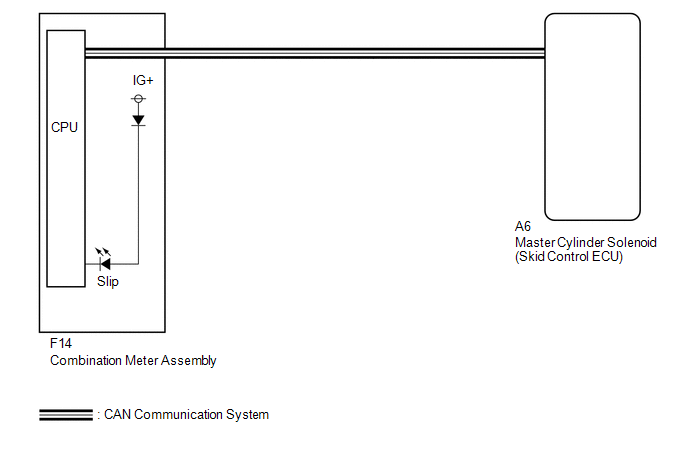
WIRING DIAGRAM
CAUTION / NOTICE / HINT
NOTICE:
When replacing the master cylinder solenoid, perform calibration (See page
.gif) ).
).
PROCEDURE
|
1. |
CHECK FOR DTC |
(a) Check for DTCs (See page ).
Result
|
Result |
Proceed to |
|---|---|
|
DTC is not output |
A |
|
DTC is output |
B |
| B | .gif) |
REPAIR CIRCUITS INDICATED BY OUTPUT DTCS |
|
.gif)
|
2. |
CHECK CAN COMMUNICATION LINE |
(a) Turn the ignition switch off.
(b) Connect the Techstream to the DLC3.
(c) Turn the ignition switch to ON.
(d) Turn the Techstream on.
(e) Select CAN Bus Check from the System Selection Menu screen and follow the
prompts on the screen to inspect the CAN bus (See page
).
OK:
CAN Bus Check indicates no malfunctions in CAN communication.
| NG | |
GO TO CAN COMMUNICATION SYSTEM (HOW TO PROCEED WITH TROUBLESHOOTING) |
|
|
3. |
READ VALUE USING TECHSTREAM (SLIP INDICATOR LIGHT) |
(a) Turn the ignition switch off.
(b) Connect the Techstream to the DLC3.
(c) Turn the ignition switch to ON.
(d) Turn the Techstream on.
(e) Enter the following menus: Chassis / ABS/VSC/TRAC / Data List.
ABS/VSC/TRAC|
Tester Display |
Measurement Item/Range |
Normal Condition |
Diagnostic Note |
|---|---|---|---|
|
Slip Indicator Light |
Slip indicator light/ ON or OFF |
ON: Indicator light on OFF: Indicator light off |
- |
(f) When performing the Slip Indicator Light Active Test, check Slip Indicator
Light in the Data List (See page ).
ABS/VSC/TRAC
|
Tester Display |
Test Part |
Control Range |
Diagnostic Note |
|---|---|---|---|
|
Slip Indicator Light |
Slip Indicator Light |
Indicator light ON/OFF |
Observe the combination meter. |
|
Result |
Proceed to |
|
|---|---|---|
|
Data List Display |
Data List Display when Performing Active Test ON/OFF Operation |
|
|
ON |
Does not change between ON and OFF |
A |
|
Changes between ON and OFF |
B |
|
|
OFF |
Does not change between ON and OFF |
A |
|
Changes between ON and OFF |
B |
|
| A | |
REPLACE MASTER CYLINDER SOLENOID |
| B | |
GO TO METER / GAUGE SYSTEM (HOW TO PROCEED WITH TROUBLESHOOTING) |
 Slip Indicator Light does not Come ON
DESCRIPTION
Refer to Slip Indicator Light Remains ON (See page
).
WIRING DIAGRAM
Refer to Slip Indicator Light Remains ON (See page
).
CAUTION / NOTICE / HINT
NOTICE:
When replacing the mast ...
 Downhill Assist Control Indicator Light Remains ON
DESCRIPTION
When the downhill assist control switch is turned on, the downhill assist control
function is available and the downhill assist control indicator light illuminates.
WIRING DIAGRAM
Ref ...
Other materials about Toyota 4Runner:
Airbag Signal Malfunction/Not Input (B15C4)
DESCRIPTION
If the DCM (Telematics Transceiver) detects an error in the communication between
the DCM (Telematics Transceiver) and center airbag sensor assembly as a result of
the DCM (Telematics Transceiver) self check, this DTC will be set.
...
TRAC OFF Indicator Light does not Come ON
DESCRIPTION
Refer to TRAC OFF Indicator Light Remains ON (See page
).
WIRING DIAGRAM
Refer to TRAC OFF Indicator Light Remains ON (See page
).
CAUTION / NOTICE / HINT
NOTICE:
When replacing the master cylinder solenoid, perform calibration (See page
...

0.009