Toyota 4Runner: System Diagram
SYSTEM DIAGRAM
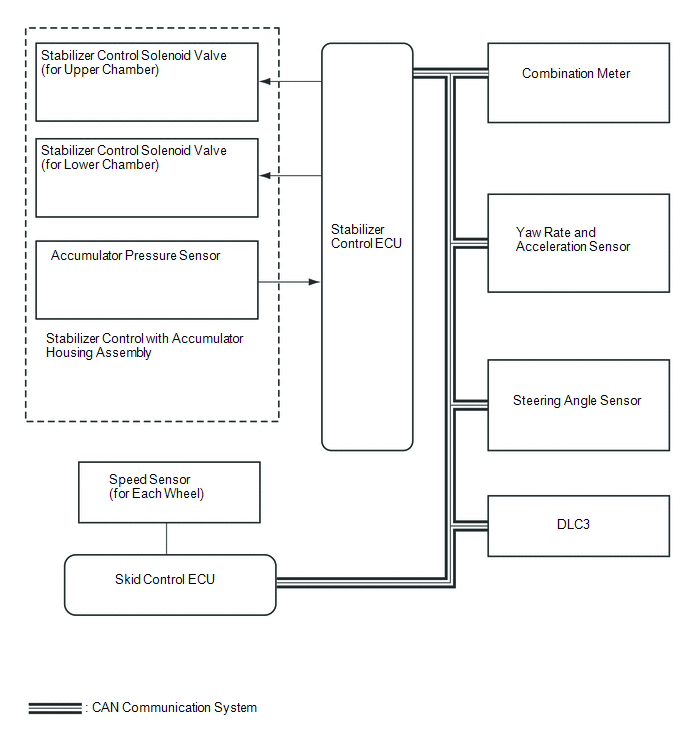 Communication Table
|
Sender |
Receiver |
Signal |
Line |
|---|---|---|---|
|
ECM |
Stabilizer control ECU |
|
CAN communication |
|
Skid control ECU |
Stabilizer control ECU |
|
CAN communication |
|
Yaw rate and acceleration sensor |
Stabilizer control ECU |
|
CAN communication |
|
Steering angle sensor |
Stabilizer control ECU |
|
CAN communication |
|
Stabilizer control ECU |
Combination meter |
KDSS indicator light signal |
CAN communication |
 Parts Location
PARTS LOCATION
ILLUSTRATION
...
 How To Proceed With Troubleshooting
CAUTION / NOTICE / HINT
HINT:
*: Use the Techstream.
PROCEDURE
1.
VEHICLE BROUGHT TO WORKSHOP
NEXT
...
Other materials about Toyota 4Runner:
Diagnostic Trouble Code Chart
DIAGNOSTIC TROUBLE CODE CHART
Front Power Seat Control System
DTC Code
Detection Item
See page
B2650
Slide Sensor Malfunction
B2651
Reclining Sensor Malfunc ...
Fuel Sender Open Detected (B1500)
DESCRIPTION
This DTC is stored when the combination meter detects a fuel sender gauge malfunction.
DTC Code
DTC Detection Condition
Trouble Area
B1500
IG voltage is 9.5 V or higher and the followin ...

0.0185