Toyota 4Runner: System Diagram
SYSTEM DIAGRAM
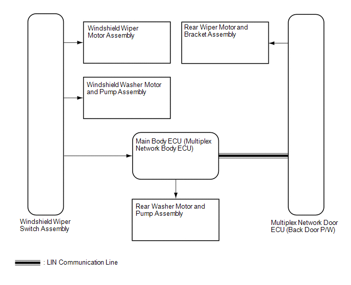
1. WIPER AND WASHER SYSTEM
 Communication Table
|
Sender |
Receiver |
Signal |
Communication Method |
|---|---|---|---|
|
Main body ECU (Multiplex network body ECU) |
Multiplex network door ECU (Back door P/W) |
Rear wiper motor operate signal |
LIN |
 Parts Location
PARTS LOCATION
ILLUSTRATION
ILLUSTRATION
...
 System Description
SYSTEM DESCRIPTION
1. WASHER LINKED OPERATION
(a) When the front wiper washer switch is in the off position and the washer
switch is turned on for approximately 0.1 seconds or more, the wipers sta ...
Other materials about Toyota 4Runner:
Dtc Check / Clear
DTC CHECK / CLEAR
1. CHECK DTC
(a) Connect the Techstream to the DLC3.
(b) Turn the engine switch on (IG).
(c) Turn the Techstream on.
(d) Enter the following menus: Body Electrical / Smart Key / Trouble Codes.
(e) Check for DTCs.
2. CLEAR DTC
(a) Conn ...
Back Door Entry Lock and Unlock Functions do not Operate
DESCRIPTION
When the back door entry lock and unlock functions do not operate, one of the
following may be malfunctioning: 1) the power door lock control system, 2) the electrical
key antenna (outside luggage) or 3) the certification ECU.
WIRING DIAGRAM
...

0.0204