Toyota 4Runner: System Description
SYSTEM DESCRIPTION
1. WASHER LINKED OPERATION
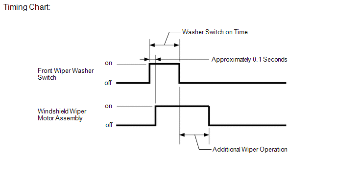
(a) When the front wiper washer switch is in the off position and the washer switch is turned on for approximately 0.1 seconds or more, the wipers start on LO at the same time as the washer fluid is sprayed.
Depending on the amount of time for which the washer switch is turned on, the washer-linked operation is performed as follows after the switch is turned off.

|
Washer Switch on Time |
Additional Wiper Operation |
|---|---|
|
0.2 sec. or less |
None |
|
Between 0.2 sec. and 1.5 sec. |
1 time |
|
1.5 sec. or more |
3 times |
2. INTERMITTENT OPERATION
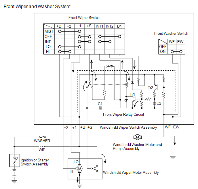
(a) The system operates the front wipers once in approximately 1.6 to 10.7 seconds when the front wiper switch is turned to the INT position. The intermittent time can be adjusted from 1.6 to 10.7 seconds by using the intermittent time adjust dial.
(b) If the front wiper switch is turned to the INT position, current flows from capacitor C1, which is already charged, through terminals INT1 and INT2 of the front wiper switch to Tr1 (transistor). When Tr1 turns on, current flows from terminal +S of the front wiper switch to terminal +1 of the front wiper switch, then to terminal +1 of the wiper motor, then to the wiper motor and finally to ground, causing the wiper motor to operate. At the same time, current flows from capacitor C1 to terminal INT1 of the front wiper switch, and then to INT2. When the current flow from capacitor C1 ends, Tr1 turns off to turn off the relay contact point and halt the wiper motor.
When the relay contact point turns off, capacitor C1 begins to charge again and Tr1 remains off until charging has been completed. This period corresponds to the intermittent time. When capacitor C1 is fully charged, Tr1 turns on and then the relay contact point turns on, causing the motor to operate again. This cycle is the intermittent operation.
The intermittent time can be adjusted by using the intermittent time adjust dial (variable resistor) to change the charge time of capacitor C1.

3. WASHER FLUID LEVEL WARNING
(a) When the volume of washer fluid decreases to below a certain level (when the level warning switch is turned on), the multi-information display in the combination meter assembly displays "LOW WASHER FLUID" to warn the driver.
 System Diagram
SYSTEM DIAGRAM
1. WIPER AND WASHER SYSTEM
Communication Table
Sender
Receiver
Signal
Communication Method
Main body ECU (Multiplex netw ...
 How To Proceed With Troubleshooting
CAUTION / NOTICE / HINT
HINT:
Use the following procedure to troubleshoot the wiper and washer system.
*: Use the Techstream.
PROCEDURE
1.
VEHICLE BROUG ...
Other materials about Toyota 4Runner:
Disassembly
DISASSEMBLY
CAUTION / NOTICE / HINT
PROCEDURE
1. REMOVE OUTER MIRROR LH
(a) Put protective tape around the outer mirror LH.
(b) Using a moulding remover, detach the 2 claws of the outer mirror
LH as shown in the illustration.
Text in Ill ...
Removal
REMOVAL
PROCEDURE
1. DISCONNECT CABLE FROM NEGATIVE BATTERY TERMINAL
(See page )
2. REMOVE NO. 1 INSTRUMENT CLUSTER FINISH PANEL GARNISH
3. REMOVE NO. 2 INSTRUMENT CLUSTER FINISH PANEL GARNISH
4. REMOVE HEATER CONTROL ASSEMBLY
5. REMOVE RADIO ...
0.025
