Toyota 4Runner: System Diagram
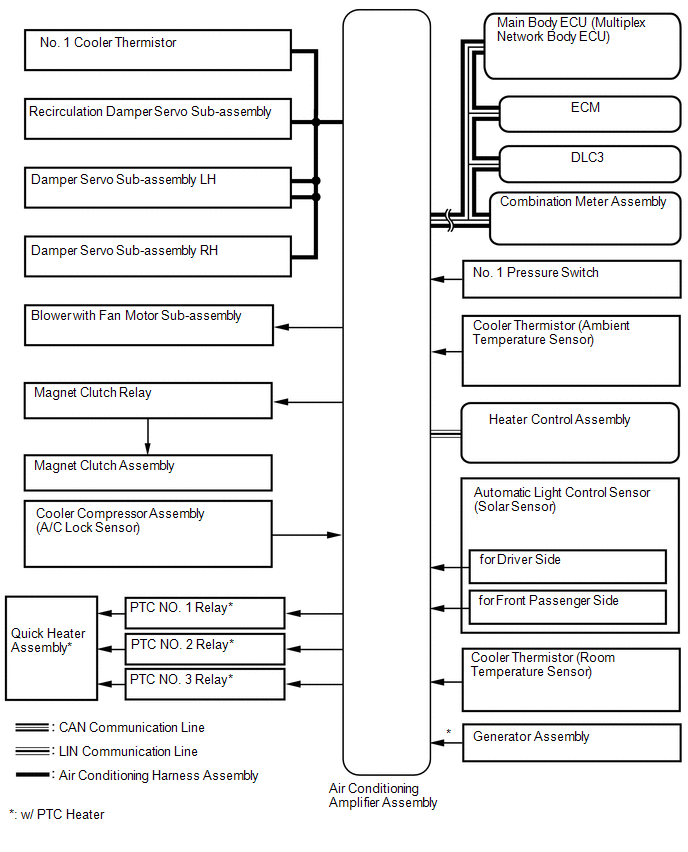
SYSTEM DIAGRAM
 Communication Table
|
Transmitter |
Receiver |
Signal |
Communication Line |
|---|---|---|---|
|
Air conditioning amplifier assembly |
ECM |
A/C idle up request signal |
CAN |
|
Heater idle up request signal |
|||
|
PTC heater control request signal* |
|||
|
Electricity load at low voltage state signal |
|||
|
Ambient temperature signal |
|||
|
Main body ECU |
Air conditioning amplifier assembly |
Main body request signal |
|
|
Combination meter assembly |
Air conditioning amplifier assembly |
Vehicle speed signal |
|
|
ECM |
Air conditioning amplifier assembly |
Engine coolant temperature signal |
|
|
Engine speed data |
|||
|
Engine type information signal |
|||
|
Heater control assembly |
Air conditioning amplifier assembly |
AUTO operation switch signal |
LIN |
|
OFF operation switch signal |
|||
|
A/C switch signal |
|||
|
Front defroster operation switch signal |
|||
|
Rear defogger operation switch signal |
|||
|
Mode operation switch signal |
|||
|
REC/FRS switch signal |
|||
|
Set temperature switch signal |
|||
|
Blower operation switch signal (up, down) |
- *: w/ PTC Heater
 System Description
SYSTEM DESCRIPTION
1. GENERAL
(a) The air conditioning system has the following controls.
Control
Outline
Neural Network Control
This control is ca ...
 How To Proceed With Troubleshooting
CAUTION / NOTICE / HINT
HINT:
Use these procedures to troubleshoot the air conditioning system.
*: Use the Techstream.
PROCEDURE
1.
VEHICLE BROUGHT TO W ...
Other materials about Toyota 4Runner:
On-vehicle Inspection
ON-VEHICLE INSPECTION
PROCEDURE
1. INSPECT HOOD SUB-ASSEMBLY
(a) Check that the clearance measurements of areas A through E are within each
standard range.
Standard:
Area
Measurement
Area
Measurement
...
Park / Neutral Position Switch Circuit
DESCRIPTION
This circuit sends the park/neutral position switch assembly signals to the clearance
warning ECU assembly.
WIRING DIAGRAM
CAUTION / NOTICE / HINT
NOTICE:
Inspect the fuses for circuits related to this system before performing the followin ...

0.0068