Toyota 4Runner: Blower Motor Circuit
DESCRIPTION
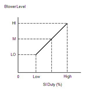
The blower with fan motor sub-assembly operates according to signals from the air conditioning amplifier assembly. The blower with fan motor sub-assembly speed signals are transmitted by changes in the duty ratio.
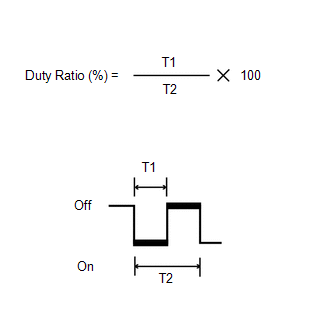
Duty Ratio:
The duty ratio is the ratio of the blower with fan motor sub-assembly on time (T1) to the total of the blower with fan motor sub-assembly on and off time (T2).
The air conditioning amplifier assembly controls the blower with fan motor sub-assembly speed.
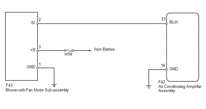
WIRING DIAGRAM
CAUTION / NOTICE / HINT
NOTICE:
Inspect the fuses for circuits related to this system before performing the following inspection procedure.
PROCEDURE
|
1. |
PERFORM ACTIVE TEST USING TECHSTREAM (BLOWER WITH FAN MOTOR) |
(a) Select the Active Test, use the Techstream to generate a control command,
and then check that the blower with fan motor sub-assembly operates (See page
.gif) ).
).
Air Conditioner
|
Tester Display |
Test Part |
Control Range |
Diagnostic Note |
|---|---|---|---|
|
Blower Motor |
Blower with fan motor sub-assembly |
Min.: 0, Max.: 31 |
- |
OK:
Blower with fan motor sub-assembly operates and blower motor speed changes.
| OK | .gif) |
PROCEED TO NEXT SUSPECTED AREA SHOWN IN PROBLEM SYMPTOMS TABLE |
|
.gif)
|
2. |
CHECK HARNESS AND CONNECTOR (BLOWER WITH FAN MOTOR - BATTERY AND BODY GROUND) |
(a) Disconnect the F43 motor connector.
(b) Measure the voltage according to the value(s) in the table below.
Standard Voltage:
|
Tester Connection |
Condition |
Specified Condition |
|---|---|---|
|
F43-3 (+B) - Body ground |
Always |
11 to 14 V |
(c) Measure the resistance according to the value(s) in the table below.
Standard Resistance:
|
Tester Connection |
Condition |
Specified Condition |
|---|---|---|
|
F43-1 (GND) - Body ground |
Always |
Below 1 Ω |
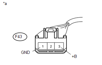
|
*a |
Front view of wire harness connector (to Blower with Fan Motor Sub-assembly) |
| NG | |
REPAIR OR REPLACE HARNESS OR CONNECTOR |
|
|
3. |
CHECK HARNESS AND CONNECTOR (AIR CONDITIONING AMPLIFIER - BLOWER WITH FAN MOTOR AND BODY GROUND) |
(a) Disconnect the F42 amplifier connector.
(b) Disconnect the F43 motor connector.
(c) Measure the resistance according to the value(s) in the table below.
Standard Resistance:
|
Tester Connection |
Condition |
Specified Condition |
|---|---|---|
|
F42-23 (BLW) - F43-2 (SI) |
Always |
Below 1 Ω |
|
F42-23 (BLW) - Body ground |
Always |
10 kΩ or higher |
|
F42-14 (GND) - Body ground |
Always |
Below 1 Ω |
| NG | |
REPAIR OR REPLACE HARNESS OR CONNECTOR |
|
|
4. |
CHECK AIR CONDITIONING AMPLIFIER ASSEMBLY (BLW SIGNAL) |
|
(a) Remove the air conditioning amplifier assembly with its connectors
still connected (See page |
|
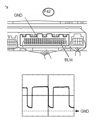
(b) Using an oscilloscope, check the waveform.
Measurement Condition|
Item |
Content |
|---|---|
|
Terminal No. (Symbol) |
F42-23 (BLW) - F42-14 (GND) |
|
Tool Setting |
1 V/DIV., 500 μs/DIV. |
|
Condition |
Ignition switch ON Blower switch LO |
OK:
Waveform is as shown in the illustration.
Text in Illustration|
*a |
Component with harness connected (Air Conditioning Amplifier Assembly) |
HINT:
Waveform varies with the blower level.
| NG | |
REPLACE AIR CONDITIONING AMPLIFIER ASSEMBLY |
|
|
5. |
REPLACE BLOWER WITH FAN MOTOR SUB-ASSEMBLY |
(a) Replace the blower with fan motor sub-assembly with a new or normally functioning
one (See page ).
(b) Operate the blower with fan motor sub-assembly to check that it functions properly.
OK:
Blower with fan motor sub-assembly operates normally.
| OK | |
END (BLOWER WITH FAN MOTOR SUB-ASSEMBLY IS FAULTY) |
| NG | |
REPLACE AIR CONDITIONING AMPLIFIER ASSEMBLY |
 Air Conditioning Control Panel Circuit
DESCRIPTION
This circuit consists of the heater control assembly and air conditioning amplifier
assembly. When the heater control assembly is operated, signals are transmitted
to the air conditio ...
 Air Conditioning Compressor Magnetic Clutch Circuit
DESCRIPTION
When the air conditioning amplifier assembly is turned on, a magnet clutch assembly
signal is sent from the MGC terminal of the air conditioning amplifier assembly.
Then, the A/C COMP ...
Other materials about Toyota 4Runner:
Speed Signal Circuit
DESCRIPTION
The vehicle speed signal consists of pulses sent to the side auto step controller
ECU assembly from the main body ECU (multiplex network body ECU).
WIRING DIAGRAM
PROCEDURE
1.
INSPECT MAIN BODY ECU (MULTIPLEX NETWORK ...
Data List / Active Test
DATA LIST / ACTIVE TEST
1. READ DATA LIST
HINT:
Using the Techstream to read the Data List allows the values or states of switches,
sensors, actuators and other items to be read without removing any parts. This non-intrusive
inspection can be very usefu ...

0.026