Toyota 4Runner: System Diagram
SYSTEM DIAGRAM
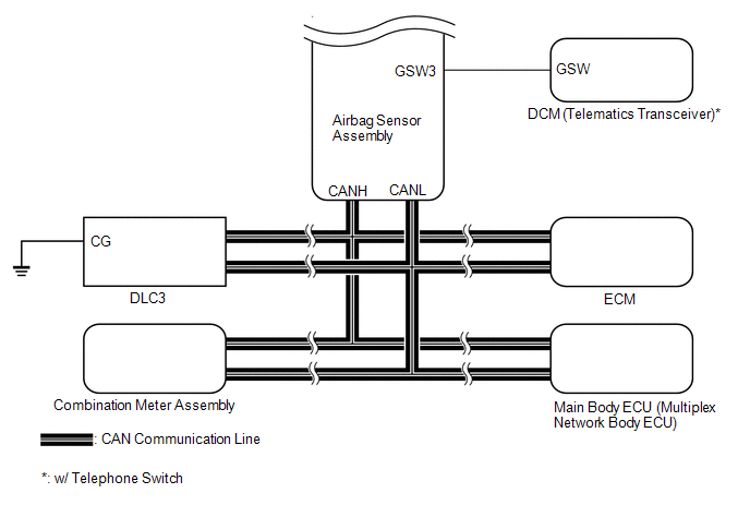
|
Transmitting ECU (Transmitter) |
Receiving ECU |
Signal |
Communication Method |
|---|---|---|---|
|
Center Airbag Sensor |
ECM |
|
CAN |
|
Center Airbag Sensor |
Main Body ECU |
Driver seat buckle switch signal |
|
|
Center Airbag Sensor |
Combination Meter |
|
|
|
Combination Meter |
Center Airbag Sensor |
|
|
|
ECM |
Center Airbag Sensor |
|
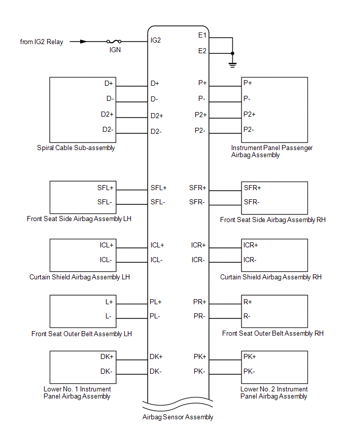
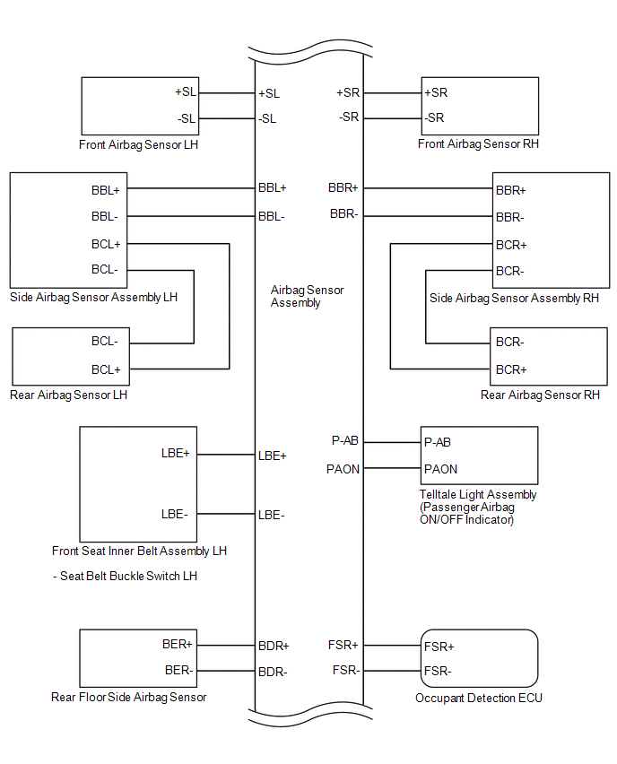
 Parts Location
PARTS LOCATION
ILLUSTRATION
ILLUSTRATION
ILLUSTRATION
ILLUSTRATION
...
 How To Proceed With Troubleshooting
CAUTION / NOTICE / HINT
HINT:
Use these procedures to troubleshoot the airbag system.
*: Use the Techstream.
PROCEDURE
1.
VEHICLE BROUGHT TO WORKSHOP
...
Other materials about Toyota 4Runner:
Installation
INSTALLATION
CAUTION / NOTICE / HINT
HINT:
Use the same procedure for the RH and LH sides.
The procedure listed below is for the LH side.
PROCEDURE
1. INSTALL FRONT DOOR INSIDE LOCKING CABLE ASSEMBLY LH
2. INSTALL FRONT DOOR LOCK REM ...
Do-it-yourself service precautions
If you perform maintenance by yourself, be sure to follow the correct
procedure as given in these sections.
CAUTION
The engine compartment contains many mechanisms and fluids that may move
suddenly, become hot, or become electrically energized. To av ...

0.007