Toyota 4Runner: Reassembly
REASSEMBLY
PROCEDURE
1. INSTALL REAR PROPELLER SHAFT UNIVERSAL JOINT SPIDER BEARING
HINT:
Use the same procedure for all rear propeller shaft universal joint spider bearing.
|
(a) Apply MP grease No. 2 to a new spider and bearings. NOTICE: Be careful not to apply too much grease. |
|
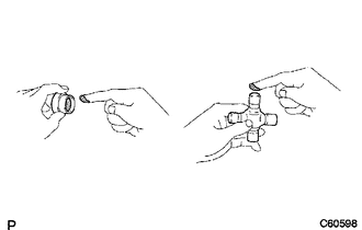
(b) Install the spider to the propeller shaft.
|
(c) Using SST, install 2 of the bearings to the spider. SST: 09332-25010 |
|
.png)
(d) Using SST, adjust both bearings so that the snap ring grooves are at maximum and equal width.
SST: 09332-25010
(e) Install 4 new snap rings of equal thickness which will allow no axial play.
.png)
HINT:
Do not reuse the snap rings.
Thickness of snap ring (Both ends thin type):
|
Parts No. |
Specified Condition |
Mark |
|---|---|---|
|
90520-25039 |
2.28 to 2.30 mm (0.0898 to 0.0906 in.) |
1 |
|
90520-25040 |
2.30 to 2.32 mm (0.0906 to 0.0913 in.) |
2 |
|
90520-25041 |
2.32 to 2.34 mm (0.0913 to 0.0921 in.) |
- |
|
90520-25042 |
2.34 to 2.36 mm (0.0921 to 0.0929 in.) |
Brown |
|
90520-25043 |
2.36 to 2.38 mm (0.0929 to 0.0937 in.) |
Blue |
|
90520-25044 |
2.38 to 2.40 mm (0.0937 to 0.0945 in.) |
6 |
|
90520-25045 |
2.40 to 2.42 mm (0.0945 to 0.0953 in.) |
7 |
|
90520-25046 |
2.42 to 2.44 mm (0.0953 to 0.0961 in.) |
8 |
|
90520-25047 |
2.44 to 2.46 mm (0.0961 to 0.0969 in.) |
.png) |
|
90520-25048 |
2.46 to 2.48 mm (0.0969 to 0.0976 in.) |
10 |
|
90520-25049 |
2.48 to 2.50 mm (0.0976 to 0.0984 in.) |
A |
|
90520-25050 |
2.50 to 2.52 mm (0.0984 to 0.0992 in.) |
B |
|
90520-25051 |
2.52 to 2.54 mm (0.0992 to 0.1000 in.) |
C |
|
90520-25052 |
2.54 to 2.56 mm (0.1000 to 0.1008 in.) |
D |
|
90520-25053 |
2.56 to 2.58 mm (0.1008 to 0.1016 in.) |
E |
|
90520-25054 |
2.18 to 2.20 mm (0.0858 to 0.0866 in.) |
J |
|
90520-25055 |
2.20 to 2.22 mm (0.0866 to 0.0874 in.) |
K |
|
90520-25056 |
2.22 to 2.24 mm (0.0874 to 0.0882 in.) |
F |
|
90520-25057 |
2.24 to 2.26 mm (0.0882 to 0.0890 in.) |
G |
|
90520-25058 |
2.26 to 2.28 mm (0.0890 to 0.0898 in.) |
H |
NOTICE:
- Use a new retainer ring.
- Use retainer rings with as close to the same thickness as possible on both ends.
(f) Using a hammer, tap the yoke until there is no clearance between the spider bearing outer race and snap ring.
HINT:
Install a new spider bearing on the sleeve side using the procedure described above.
2. INSPECT PROPELLER SHAFT ASSEMBLY
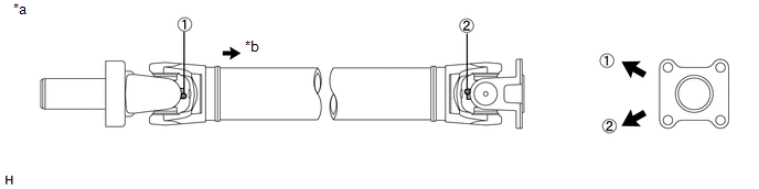
HINT:
When replacing the spider bearing, be sure that the grease fitting assembly hole is facing to the direction shown in the illustration.
 Text in Illustration
|
*a |
Spider grease fitting assembly direction for front propeller shaft assembly |
*b |
Rear Side |
3. INSPECT REAR PROPELLER SHAFT UNIVERSAL JOINT SPIDER BEARING
.gif)
 Inspection
INSPECTION
PROCEDURE
1. INSPECT PROPELLER SHAFT ASSEMBLY
(a) Using a dial indicator, check the propeller shaft runout.
Maximum runout:
0.4 mm (0.0157 in.)
If the shaft runout i ...
 Installation
INSTALLATION
PROCEDURE
1. INSTALL PROPELLER SHAFT ASSEMBLY
(a) Remove SST from the extension housing.
SST: 09325-40010
(b) Install the propeller shaft assembly to the extension housing.
(c) Alig ...
Other materials about Toyota 4Runner:
Back Door Courtesy Switch Circuit
DESCRIPTION
The multiplex network door ECU receives a back door open/closed signal from the
back door lock.
WIRING DIAGRAM
PROCEDURE
1.
READ VALUE USING TECHSTREAM (BACK DOOR COURTESY LIGHT SWITCH)
(a) Using the Techstr ...
Audio system types
Without navigation system and Display Audio system
Type A: CD player with changer controller and AM/FM radio
Type B: CD player with changer controller and AM/FM radio
Type C: CD player with changer and AM/FM radio
With Display Audio system
Owners ...

0.007