Toyota 4Runner: System Diagram
SYSTEM DIAGRAM
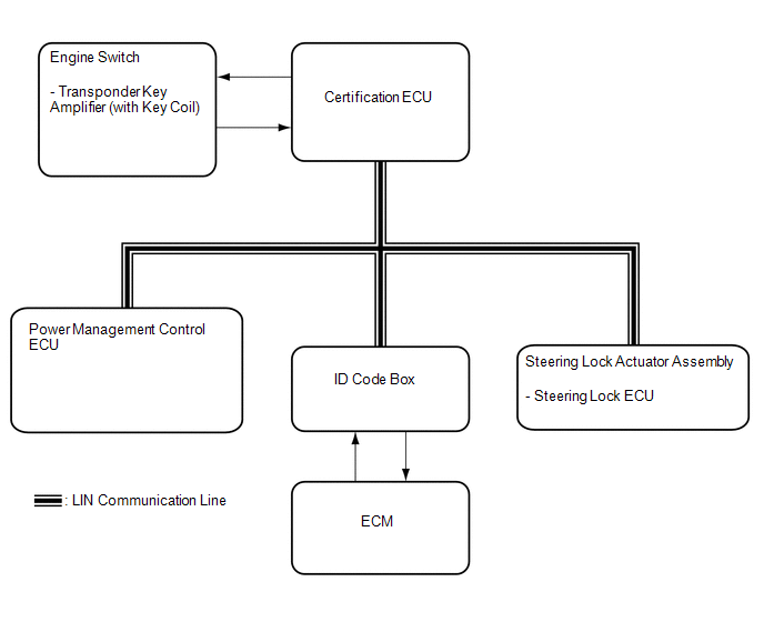 Communication Table
|
Sender |
Receiver |
Signal |
Line |
|---|---|---|---|
|
Certification ECU |
Power management control ECU |
|
LIN |
|
Power management control ECU |
Certification ECU |
|
|
|
ID code box |
Certification ECU |
|
|
|
Steering lock ECU |
|
||
|
Steering lock ECU |
Certification ECU |
L code verification signal |
 System Description
SYSTEM DESCRIPTION
1. ENGINE IMMOBILISER SYSTEM DESCRIPTION
(a) The engine immobiliser system determines whether or not to enable starting
of the SFI system based on a comparison of the key ID cod ...
 How To Proceed With Troubleshooting
CAUTION / NOTICE / HINT
HINT:
Use these procedures to troubleshoot the engine immobiliser system.
*: Use the Techstream.
PROCEDURE
1.
VEHICLE BROUGHT TO ...
Other materials about Toyota 4Runner:
Precaution
PRECAUTION
CAUTION:
Replace any faulty parts of the seat belt systems (outer belt, inner belt, bolts,
nuts, adjustable shoulder anchor, tether anchor hardware and other related parts).
When inspecting a vehicle that was in a collision, be sure to check a ...
Stop Light Control Relay Malfunction (C1380)
DESCRIPTION
Upon receiving the hill-start assist control operating signal from the master
cylinder solenoid (skid control ECU), the Stop light control relay (Stop light switch
assembly) contact turns on and the stop lights come on.
DTC No.
...

0.0069