Toyota 4Runner: System Diagram
SYSTEM DIAGRAM
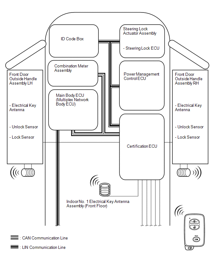
 Communication Table
|
Sender |
Receiver |
Signal |
Line |
|---|---|---|---|
|
Main Body ECU |
Certification ECU |
|
CAN |
|
Power Management Control ECU |
Certification ECU |
|
LIN |
|
Combination Meter Assembly |
|
Vehicle speed signal |
CAN |
|
Steering Lock ECU |
Certification ECU |
|
LIN |
|
ID Code Box |
Certification ECU |
Matching request random number signal |
LIN |
|
Certification ECU |
Combination Meter Assembly |
|
CAN |
|
Certification ECU |
Main Body ECU |
|
CAN |
|
Certification ECU |
Power Management Control ECU |
|
LIN |
|
Certification ECU |
ID Code Box |
Replay ID code signal |
LIN |
|
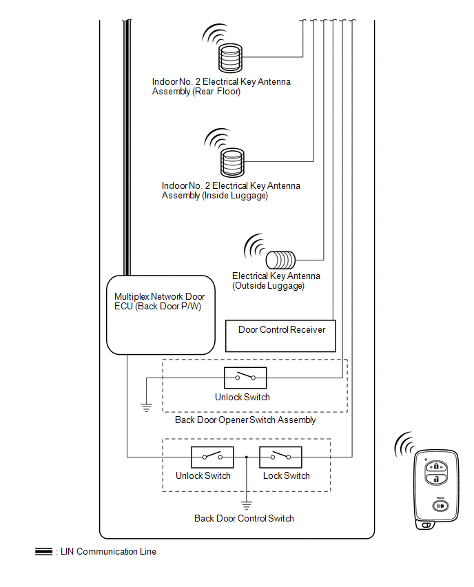
Multiplex Network Door ECU (Back Door P/W) |
Main Body ECU |
Back door control switch signal |
LIN |
 System Description
SYSTEM DESCRIPTION
CAUTION:
If using a pacemaker, be sure to read the manual of the pacemaker before using
the key, as the radio waves of the key may affect the pacemaker.
1. SMART KEY SYSTEM DES ...
 Customize Parameters
CUSTOMIZE PARAMETERS
1. CUSTOMIZING FUNCTION WITH TECHSTREAM
HINT:
The following items can be customized.
NOTICE:
When the customer requests a change in a function, first make sure that
...
Other materials about Toyota 4Runner:
Air Conditioning Compressor Magnetic Clutch Circuit
DESCRIPTION
When the air conditioning amplifier assembly is turned on, a magnet clutch assembly
ON signal is sent from the MGC terminal of the air conditioning amplifier assembly.
Then, the A/C COMP relay turns on to operate the magnet clutch assembly.
W ...
Installation
INSTALLATION
PROCEDURE
1. INSTALL VOLTAGE INVERTER ASSEMBLY
(a) Install the voltage inverter with the 3 bolts.
Torque:
7.5 N·m {76 kgf·cm, 66 in·lbf}
(b) Connect the 2 connectors.
2. INSTALL DECK TRIM SIDE PANEL ASSEMBLY RH
3. INSTALL FRONT DECK ...

0.0102