Toyota 4Runner: System Description
SYSTEM DESCRIPTION
CAUTION:
If using a pacemaker, be sure to read the manual of the pacemaker before using the key, as the radio waves of the key may affect the pacemaker.
1. SMART KEY SYSTEM DESCRIPTION
(a) In addition to conventional mechanical key and wireless door lock control functions, the smart key system enables door locking/unlocking, steering lock releasing, engine control system starting and back door opening without operating the key. The only requirement is that the key is in the possession of the user.
- This system is controlled by the certification ECU. When the certification ECU detects the presence of the key in one of the detection areas, it identifies and checks the ID code, and outputs operation signals to the related ECU in accordance with their functions.
- The detection areas are formed by 6 antennas.
2. DETECTION AREA
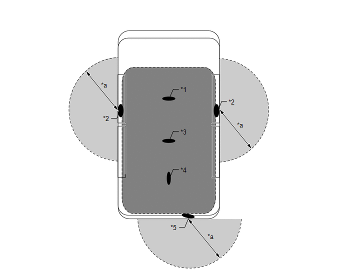 Text in Illustration
|
*1 |
Indoor No. 1 Electrical Key Antenna Assembly (Front Floor) |
*2 |
Electrical Key Antenna |
|
*3 |
Indoor No. 2 Electrical Key Antenna Assembly (Rear Floor) |
*4 |
Indoor No. 2 Electrical Key Antenna Assembly (Inside Luggage) |
|
*5 |
Electrical Key Antenna (Outside Luggage) |
- |
- |
|
*a |
Approximately 0.7 to 1.0 m (2.30 to 3.28 ft.) |
- |
- |
.png) |
Interior Detection Area |
.png) |
Exterior Detection Area |
(a) Precautions for the entire system:
- Be sure to carry the key during inspection of the smart key system.
- As weak radio waves are used to detect the key, the key detection area
may decrease, or the key may not be detected correctly in the following
situations.
- The key battery is depleted.
- Any facilities that generate strong radio waves, such as a TV tower, power plant, broadcast station or gas station, are located near the inspection site.
- A wireless device, such as a cell phone, is carried with the key.
- The key is in contact with or covered by metal.
- Electric wave type keyless entry systems are being operated nearby.
- The key is located near a device that generates high voltage or noise.
- Film with some metallic content is applied to the back glass.
HINT:
In this case, remove the film or unlock the door using the mechanical key.
- Even if the key is in the vehicle exterior key detection area, the key may not operate properly due to the vehicle body design.
- The key may not be detected correctly if it is around the vehicle windows, door handles or bumpers, even when it is in the detection area outside the vehicle.
- The key may not be detected correctly if it is on the instrument panel or floor, or in the glove box, even when it is in the detection area inside the vehicle.
- The key may not operate if the key is not held properly.
- The smart key system does not operate under the following conditions:
- The smart key system is canceled.
- The key battery is completely depleted (the indicator does not blink when pushing any of the switches on the key).
3. FUNCTION OF MAIN COMPONENTS
|
Component |
Function |
|---|---|
|
Certification ECU |
Controls the smart key system in accordance with signals from each antenna, various switches, ECUs and the key.
|
|
Main body ECU |
|
|
Power management control ECU |
Controls the push button start function in accordance with signals from various switches, ECUs and the combination meter.
|
|
Multiplex network door ECU (back door P/W) |
Transmits a back door window open (door unlock) request signal to the certification ECU. |
|
ID code box |
|
|
Indoor electrical key antenna assembly (front floor, rear floor and inside luggage) |
Receives a request signal from the certification ECU and forms the detection area in the vehicle interior. |
|
Door control receiver |
Receives the ID code from the key in the detection area and transmits it to the certification ECU. |
|
Electrical key antenna (outside luggage) |
Receives a request signal from the certification ECU and forms the detection area around the back door. |
|
Back door control switch |
|
|
Back door opener switch assembly |
Transmits a door unlock request signal to the certification ECU. |
|
Front door outside handle assembly (for driver, front passenger side doors) |
|
|
Key |
Consists of a mechanical key, a transmitter for wireless door lock control and a transceiver for the smart key system. |
|
Wireless door lock buzzer Combination meter assembly
|
When the certification ECU detects human errors, such as those below, it warns the driver by sounding the wireless door lock buzzer, displays information and sounds the buzzer in accordance with the request signal from the ECU. Example:
|
4. CONSTRUCTION AND OPERATION
(a) Key:
A total of 7 keys can be registered.
(1) Electrical key transmitter:
The electrical key transmitter consists of a mechanical key, a transmitter function for the wireless door lock control and a transceiver for the smart key system.
- The transceiver function for the smart key system receives the signals from the antennas and sends the ID code to the door control receiver.
- The transmitter function for the wireless door lock control has a lock switch, unlock switch and panic switch.
- The mechanical key can lock/unlock all the doors. To lock or unlock the doors, insert the key into the door key cylinder, and then turn it to the lock or unlock position.
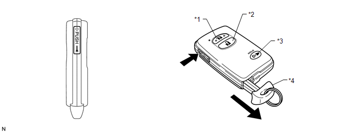 Text in Illustration
|
*1 |
Lock Switch |
*2 |
Unlock Switch |
|
*3 |
Panic Switch |
*4 |
Mechanical Key |
(b) Antenna (front door, front floor, rear floor, inside luggage and outside luggage):
Each antenna transmits the request signal received from the certification ECU, and forms a key detection area to detect the presence of a key. The detection area formed by the front door antenna and outside luggage antenna is approximately 0.7 to 1.0 m (2.30 to 3.28 ft.) from the outside handle of the front door and rear bumper.
- The detection area of the front door antenna is formed by transmitting a request signal every 0.25 seconds while the engine switch is off and all the doors are locked. In this way, it detects the proximity of a key. During entry lock, the detection area is formed with the lock sensor on.
- The detection area of the outside luggage antenna is formed when the unlock switch is on.
- The detection area of the indoor antennas (front floor, rear floor and inside luggage) is formed when the driver door is open or closed, during starting, when a warning is activated, or when the lock sensor is on.
5. ENTRY FUNCTION OPERATION
(a) The smart key system has the following functions.
|
Function |
Outline |
|---|---|
|
Mechanical Key |
Operation is the same as a conventional mechanical key. |
|
Wireless Door Lock Control |
This function remotely locks and unlocks all the doors and the back door. Operation is the same as the wireless door lock control system. However, the receiver in the certification ECU uses the door control receiver to control locking and unlocking. |
|
Entry Unlock |
When the key is located in the detection area of the electrical key antenna, the door can be unlocked by touching the inside of the front door outside handle. |
|
Entry Unlock Mode Switching (See page
|
Changes the doors that can be unlocked with the entry unlock function between 2 modes.
|
|
Entry Lock |
|
|
Entry Back Door Unlock |
When the key is in the detection area of the electrical key antenna (outside luggage), the door can be unlocked by pressing the unlock switch on the back door control switch or the back door opener switch. |
|
Back Door Power Window Function |
|
|
Key Lock-in Prevention |
|
|
Entry Illumination |
When a person carrying the key enters the detection area, the door enters unlock standby mode and the room light illuminates. |
|
Warning |
When any of the situations below occur, the smart key system causes the certification ECU (smart key ECU assembly) to sound the wireless door lock buzzer and a buzzer in the combination meter assembly with a message to appear on the multi-information display in order to alert the driver.
|
|
Battery Saving |
If the key is constantly located within the detection area of the door antenna, the system maintains periodic communication with the key. Therefore, if the vehicle remains parked in that state for a long time, the key battery and vehicle battery may be drained. For this reason, the vehicle has controls for saving battery power. |
|
Key Cancel (See page |
The following key functions can be canceled:
|
6. ENTRY UNLOCK FUNCTION
(a) The detection area is formed by communication between an electrical key antenna and the certification ECU when the door is locked in order to detect the person carrying the key.
(b) When the person carrying the key enters the detection area around the vehicle, the matching of the ID codes for an electrical key antenna and key is automatically performed. After the matching is completed, the door enters unlock standby mode.
(c) In unlock standby mode, the electrical key antenna built into the outside handle starts operating. If the outside handle is held (the back side of the handle is touched), the door unlock operation is performed. At this time, the hazard warning lights blink twice.
(d) If any of the doors are not opened after a door unlock operation, all the doors automatically lock after 30 seconds.
7. ENTRY LOCK FUNCTION
(a) After leaving the vehicle while carrying the key, touch the lock sensor on the outside handle or push the unlock switch on the back door control switch when all the doors are closed.
(b) The certification ECU determines whether the key is located inside or outside of the cabin based on the information from an electrical key antenna and indoor electrical key antenna. Then matching of the ID codes is performed.
(c) When the matching result shows that the key is not detected inside the vehicle and the ID codes of the key and electrical key antenna match, the door lock function operates. At this time, the hazard warning lights blink once.
(d) If the key is located inside of the cabin, the door lock function does not operate and the alarm buzzer (beep sound) sounds for 2 seconds.
8. ENTRY BACK DOOR UNLOCK FUNCTION
Stand in front of the back door with the key and push the unlock switch on the back door control switch or back door opener switch to start the matching of the ID codes for the electrical key antenna. If the ID codes match, the back door unlock operation is performed.
9. BACK DOOR POWER WINDOW FUNCTION
(a) Pressing the unlock switch on the back door control switch for approximately 1 second or more operates the back door window open operation.
(b) Pressing the lock switch on the back door control switch for approximately 1 second or more operates the back door window close operation.
(c) If the back door power window function is operating and the unlock switch or lock switch is released, the back door power window operation stops.
(d) The wireless buzzer sounds while the back door power window function is operating.
HINT:
For more information about the back door power window function, refer to the
power window control system (See page .gif) ).
).
10. PREVENTION OF KEY LOCK-IN FUNCTION
(a) If the key is in the cabin, the doors are closed and the entry lock operation is attempted (the lock sensor on the door outside handle is touched), the system determines that the key is located in the cabin and unlocks the doors.
(b) If the back door is closed and the lock switch is pressed with the key in the vehicle and the other doors locked, the alarm sounds and the back door does not lock.
11. ENTRY ILLUMINATION FUNCTION
In order to improve ease of entering and exiting the vehicle at night, the vehicle lights illuminate when the key is brought near the vehicle.
12. WARNING FUNCTION
(a) General:
When any of the situations below occur, the smart key system causes the certification ECU (smart key ECU assembly) to sound the wireless door lock buzzer and a buzzer in the combination meter assembly with a message to appear on the multi-information display in order to alert the driver.
|
Warning Function Operation Condition |
Situation |
|---|---|
|
Shift lever not in P (power source cut reminder) vehicle exit warning |
A |
|
Key reminder warning |
B |
|
Shift lever in P (power source cut reminder) vehicle exit warning |
C |
|
Passenger has brought electrical key transmitter sub-assembly out of vehicle warning |
D |
|
Key is not within detection area warning |
E |
|
Starting to drive without key warning |
F |
|
Key left inside vehicle warning |
G |
|
Door ajar entry lock warning |
H |
|
Key lock-in prevention warning |
I |
|
Key battery low warning |
J |
|
Steering not unlocked warning |
K |
|
Steering lock system error warning |
L |
|
Power source malfunction warning |
M |
|
Engine start operation assistance display |
N |
|
Power OFF operation assistance display |
O |
|
Automatic power OFF activation notification |
P |
|
Immobiliser verification completion notification |
Q |
(b) Situation A: The engine is left running and the shift lever is in a position other than P when the driver gets out of the vehicle.
There are 2 patterns for this situation.
(1) Pattern 1: When the engine is left running and the shift lever is in a position other than P, the driver opens the door and attempts to get out of the vehicle.
|
Item |
Content |
|---|---|
|
Reason for warning |
Sudden vehicle start, vehicle theft, vehicle roll-away |
|
Warning Start Condition (All conditions are met) |
|
|
Warning description |
|
|
Warning Stop Condition (Any condition is met) |
|
(2) Pattern 2: Under the situation of pattern 1, the driver closes the door and attempts to leave the vehicle while holding the electrical key transmitter sub-assembly.
|
Item |
Content |
|---|---|
|
Reason for warning |
Sudden vehicle start, vehicle theft, vehicle roll-away |
|
Warning Start Condition (All conditions are met) |
|
|
Warning description |
|
|
Warning Stop Condition (Any condition is met) |
|
(c) Situation B: The key reminder sounds.
(1) When the driver door is open, the driver turns the engine switch on (ACC) and attempts to leave the vehicle.
|
Item |
Content |
|---|---|
|
Reason for warning |
Vehicle theft |
|
Warning Start Condition (All conditions are met) |
Condition 1:
Condition 2:
|
|
Warning description |
Buzzer in combination meter assembly sounds continuously ("pong" sound). |
|
Warning Stop Condition (Any condition is met) |
|
(d) Situation C: The engine is left running with the shift lever in P when the driver gets out of the vehicle.
There are 2 patterns for this situation.
(1) Pattern 1: When the engine is left running with the shift lever in P, the driver closes the driver door and attempts to leave the vehicle while carrying the electrical key transmitter sub-assembly.
|
Item |
Content |
|---|---|
|
Reason for warning |
Vehicle theft |
|
Warning Start Condition (All conditions are met) |
|
|
Warning description |
|
|
Warning Stop Condition (Any condition is met) |
|
(2) Pattern 2: Under the situation of pattern 1, the driver closes the door and attempts to leave the vehicle while holding the electrical key transmitter sub-assembly.
|
Item |
Content |
|---|---|
|
Reason for warning |
Vehicle theft |
|
Warning Start Condition (All conditions are met) |
|
|
Warning description |
|
|
Warning Stop Condition (Any condition is met) |
|
(e) Situation D: The engine is left running when a passenger gets out of the vehicle while carrying the electrical key transmitter sub-assembly.
(1) When the engine is left running, a passenger leaves the vehicle while carrying the electrical key transmitter sub-assembly.
|
Item |
Content |
|---|---|
|
Reason for warning |
Engine cannot be restarted |
|
Warning Start Condition (All conditions are met) |
|
|
Warning description |
|
|
Warning Stop Condition (Any condition is met) |
|
(f) Situation E: The electrical key transmitter sub-assembly is not in the interior or exterior detection areas.
(1) When the electrical key transmitter sub-assembly is not in the vehicle or the transmitter battery is depleted, the driver attempts to start the engine or turn the engine switch on (IG).
|
Item |
Content |
|---|---|
|
Reason for warning |
User confusion prevention |
|
Warning Start Condition (All conditions are met) |
|
|
Warning description |
|
|
Warning Stop Condition (Any condition is met) |
|
(g) Situation F: The vehicle is driven without an electrical key transmitter sub-assembly.
(1) When the vehicle starts moving without the registered electrical key transmitter sub-assembly in the vehicle.
|
Item |
Content |
|---|---|
|
Reason for warning |
Engine cannot be restarted |
|
Warning Start Condition (All conditions are met) |
|
|
Warning description |
|
|
Warning Stop Condition (Any condition is met) |
|
(h) Situation G: The electrical key transmitter sub-assembly is left in the vehicle.
(1) The lock sensor on a door outside handle assembly is touched to perform entry lock with the electrical key transmitter sub-assembly left in the vehicle.
|
Item |
Content |
|---|---|
|
Reason for warning |
Vehicle theft |
|
Warning Start Condition (All conditions are met) |
|
|
Warning description |
|
|
Warning Stop Condition (Any condition is met) |
|
(i) Situation H: Door is ajar.
(1) The lock sensor on the door outside handle assembly is touched to perform entry lock with a door open.
|
Item |
Content |
|---|---|
|
Reason for warning |
Vehicle theft |
|
Warning Start Condition (All conditions are met) |
|
|
Warning description |
The wireless door lock buzzer sounds continuously for 5 seconds. |
|
Warning Stop Condition (Any condition is met) |
|
(j) Situation I: The electrical key transmitter sub-assembly is locked inside the vehicle.
(1) With a door open and the electrical key transmitter sub-assembly in the vehicle, the lock knob is locked and then the door is closed with the door handle being pulled.
|
Item |
Content |
|---|---|
|
Reason for warning |
Vehicle theft |
|
Warning Start Condition (All conditions are met) |
|
|
Warning description |
|
|
Warning Stop Condition (Any condition is met) |
|
(k) Situation J: The transmitter battery is weak.
(1) The vehicle is driven using an electrical key transmitter sub-assembly that has a low transmitter battery.
|
Item |
Content |
|---|---|
|
Reason for warning |
Usability function |
|
Warning Start Condition (All conditions are met) |
|
|
Warning description |
|
(l) Situation K: The steering wheel cannot be released.
(1) The steering wheel cannot be released, thus the engine is prevented from starting.
|
Item |
Content |
|---|---|
|
Reason for warning |
Usability function |
|
Warning Start Condition |
Steering wheel cannot be unlocked. |
|
Warning description |
|
|
Warning Stop Condition (Any condition is met) |
|
(m) Situation L: The steering lock is malfunctioning.
(1) Malfunction that interferes with the steering lock ECU (steering lock actuator assembly) operation, has been detected.
|
Item |
Content |
|---|---|
|
Reason for warning |
Malfunction detection |
|
Warning Start Condition |
The steering lock ECU (steering lock actuator assembly), driver of the power management control ECU or unlock detection switch is malfunctioning. |
|
Warning description |
|
|
Warning Stop Condition (Any condition is met) |
|
(n) Situation M: The power management control ECU is malfunctioning.
(1) When an internal malfunction occurs in the power management control ECU has been detected.
|
Item |
Content |
|---|---|
|
Reason for warning |
Malfunction detection |
|
Warning Start Condition |
The power management control ECU is malfunctioning. |
|
Warning description |
|
|
Warning Stop Condition |
The system returns to normal. |
(o) Situation N: The engine does not start.
There are 3 patterns for this situation.
(1) Pattern 1: When the engine switch is pressed, the electrical key transmitter sub-assembly cannot be detected in the vehicle two times in a row.
|
Item |
Content |
|---|---|
|
Reason for warning |
Usability function |
|
Warning Start Condition (All conditions are met) |
|
|
Warning description |
|
|
Warning Stop Condition |
The electrical key transmitter sub-assembly is in the vehicle. |
(2) Pattern 2: A warning message appears on the multi-information display when the driver does not follow the proper procedure to start the vehicle.
|
Item |
Content |
|---|---|
|
Reason for warning |
Usability function |
|
Warning Start Condition (All conditions are met) |
|
|
Warning description |
|
|
Warning Stop Condition (Any condition is met) |
|
(3) Pattern 3: A message indicating how to start the engine appears on the multi-information display when the shift lever is in a position in which the engine cannot be started.
|
Item |
Content |
|---|---|
|
Reason for warning |
Usability function |
|
Warning Start Condition (All conditions are met) |
|
|
Warning description |
|
|
Warning Stop Condition (Any condition is met) |
|
(p) Situation O: The engine switch cannot be turned off.
(1) A warning message appears on the multi information display when the driver attempts to turn the engine switch off with the shift lever in any position other than P or N.
|
Item |
Content |
|---|---|
|
Reason for warning |
Usability function |
|
Warning Start Condition (All conditions are met) |
|
|
Warning description |
|
|
Warning Stop Condition (Any condition is met) |
|
(q) Situation P: Auto power off operation occurs.
(1) A warning message appears on the multi-information display when automatic power off operation occurs.
|
Item |
Content |
|---|---|
|
Reason for warning |
Vehicle battery saving function |
|
Warning Start Condition (All conditions are met) |
|
|
Warning description |
"AUTO POWER OFF TO CONSERVE BATTERY" is displayed on multi-information display in combination meter assembly for 10 seconds. |
|
Warning Stop Condition |
The engine switch is turned on (ACC) or on (IG). |
(r) Situation Q: Immobiliser system certification completion occurs.
(1) When an electrical key transmitter sub-assembly with a depleted transmitter battery is held near to the engine switch while depressing the brake.
|
Item |
Content |
|---|---|
|
Reason for warning |
Usability function |
|
Warning Start Condition |
Electrical key transmitter sub-assembly certification result is OK. |
|
Warning description |
|
|
Warning Stop Condition (Any condition is met) |
|
13. BATTERY SAVING
(a) When the smart key system (for Entry Function) is operating, the vehicle performs key detection operations every 0.25 seconds. Therefore, if the vehicle left as is for a long period of time, the battery may become fully depleted. The following controls help reduce the rate at which the battery is depleted.
(1) If the engine is not started for 5 days or more, periodic signal transmission from the electrical key antennas stops. However, the doors can still be unlocked by touching the unlock sensor of a front door outside handle assembly.
(2) If the engine is not started for 14 days or more, the lock and unlock sensors of the front passenger side door outside handle assembly are disabled. Therefore, only the unlock sensor of the front door outside handle assembly of the driver side door can be used to unlock the doors.
(3) If 10 minutes or more elapse while the key is in the detection area (including the vehicle interior), smart key system (for Entry Function) control stops operating.
(b) To restore operation of the smart key system (for Entry Function), perform any of the following operations.
(1) While carrying the key, touch the lock and unlock sensor of the front door outside handle assembly of the driver side door and perform a door lock or unlock operation.
(2) Lock or unlock the doors with the wireless operation.
(3) Insert the mechanical key into the door key cylinder of the driver side door and lock or unlock the doors.
(c) Key battery and vehicle battery saving function:
While the smart key system is operating, if the key is constantly located within the vehicle exterior detection area of the doors, the system maintains periodic communication with the key. Therefore, if the vehicle remains parked in that state for a long time, the key battery and the vehicle battery may be drained. For this reason, if this state continues for more than 10 minutes, the smart key system is automatically deactivated.
Reinstatement Conditions:
- A wireless door lock control signal (lock, unlock) is input and the ID code matches.
- A user carries the key and touches the lock sensor on a door outside handle assembly.
- The driver door is locked or unlocked by the mechanical key.
14. KEY DIAGNOSTIC MODE (Using the Techstream)
HINT:
Key diagnostic mode checks if the electrical key transmitter within a selected antenna detection area is operating normally. The results are output through the wireless door lock buzzer (in the front fender).
(a) Connect the Techstream to the DLC3.
(b) Turn the engine switch on (IG).
(c) Turn the Techstream on.
(d) Enter the following menus: Body Electrical / Smart Key / Utility / Key Communication Check.
(e) Check the values by referring to the table below.
Smart Key|
Tester Display |
Inspection Range |
|---|---|
|
Overhead + Driver Side*1 |
Electrical key antenna (for Driver Side) |
|
Overhead + Passenger Side*2 |
Electrical key antenna (for Front Passenger Side) |
|
Overhead + Front Room*3 |
Indoor No. 1 electrical key antenna (Front Floor) |
|
Overhead + Rear Room*4 |
Indoor No. 2 electrical key antenna (Rear Floor) |
|
Overhead + Back Door (inside)*5 |
Indoor No. 2 electrical key antenna (Inside Luggage) |
|
Overhead + Back Door*6 |
Electrical key antenna (Outside Luggage) |
(f) When the electrical key transmitter is brought near the selected antenna, check that the wireless door lock buzzer sounds.
(1) *1: Electrical key antenna (for driver side)
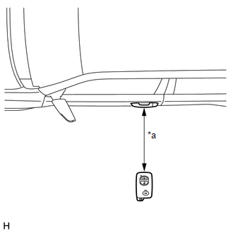 Text in Illustration
|
*a |
0.7 to 1.0 m (2.30 to 3.28 ft.) |
HINT:
- Hold the key at the same height as the door outside handle (0.7 to 1.0 m [2.30 to 3.28 ft.]). Pay attention to the direction of the key in the illustration.
- *2: Perform the same inspection above for the other electrical key antenna (for front passenger side).
(2) *3: Indoor No. 1 electrical key antenna (front floor)
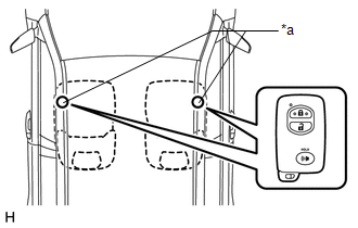 Text in Illustration
|
*a |
Inspection Point |
HINT:
Place the electrical key transmitter on the driver or front passenger seat cushion.
(3) *4: Indoor No. 2 electrical key antenna (rear floor)
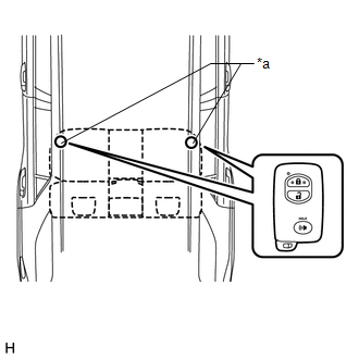 Text in Illustration
|
*a |
Inspection Point |
HINT:
Pay attention to the direction of the key in the illustration.
(4) *5: Indoor No. 2 electrical key antenna (inside luggage)
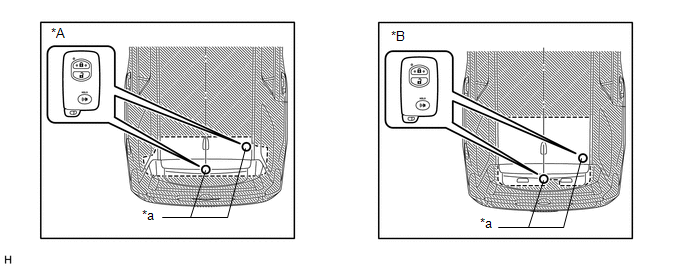 Text in Illustration
|
*A |
w/ Rear No. 2 Seat Assembly |
|
*B |
w/o Rear No. 2 Seat Assembly |
|
*a |
Inspection Point |
HINT:
Pay attention to the direction of the key in the illustration.
(5) *6: Electrical key antenna (outside luggage)
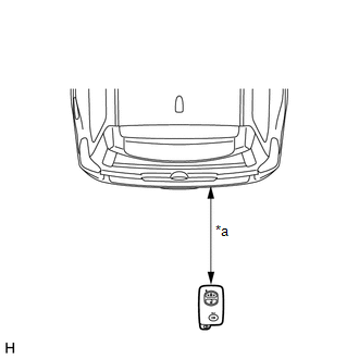 Text in Illustration
|
*a |
0.7 to 1.0 m (2.30 to 3.28 ft.) |
HINT:
Hold the electrical key transmitter at the same height as the rear bumper upper surface. Pay attention to the direction of the key in the illustration.
 Parts Location
PARTS LOCATION
ILLUSTRATION
ILLUSTRATION
ILLUSTRATION
ILLUSTRATION
ILLUSTRATION
...
 System Diagram
SYSTEM DIAGRAM
Communication Table
Sender
Receiver
Signal
Line
Main Body ECU
Certification ECU
Front ...
Other materials about Toyota 4Runner:
Installation
INSTALLATION
PROCEDURE
1. INSTALL BACK DOOR OUTSIDE GARNISH (w/o Smart Key System)
(a) Attach the 3 clips to install the back door outside garnish.
(b) Install the 4 nuts.
(c) Connect the connector.
2. INSTALL BACK DOOR OUTSIDE GARNISH (w/ Smart Key Syst ...
On-vehicle Inspection
ON-VEHICLE INSPECTION
CAUTION / NOTICE / HINT
HINT:
Use the same procedure for the RH and LH sides.
The procedure listed below is for the LH side.
PROCEDURE
1. CHECK SIDE AIRBAG SENSOR ASSEMBLY LH (VEHICLE NOT INVOLVED IN COLLISION)
(a) ...
0.0073
