Toyota 4Runner: System Diagram
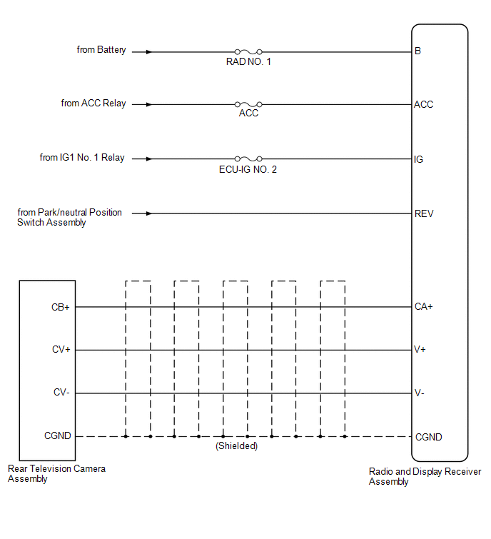
SYSTEM DIAGRAM
 Precaution
PRECAUTION
1. IGNITION SWITCH EXPRESSION
HINT:
The type of ignition switch used on this model differs according to the specifications
of the vehicle. The expressions listed in the table below are ...
 System Description
SYSTEM DESCRIPTION
1. GENERAL
(a) To assist the driver with parking the vehicle by displaying an image of the
area behind the vehicle, this system has a rear television camera assembly mounted
o ...
Other materials about Toyota 4Runner:
System Diagram
SYSTEM DIAGRAM
Communication Table
Transmitting ECU
Receiving ECU
Signal
Communication Method
Multiplex network master switch assembly
Front power window regulator motor ...
Engine immobilizer system
The vehicle’s keys have built-in transponder chips that prevent the engine
from starting if a key has not been previously registered in the vehicle’s
on-board computer.
Never leave the keys inside the vehicle when you leave the vehicle.
Vehicles wi ...
© 2016-2026 | www.to4runner.net

0.0287
0.0287