Toyota 4Runner: Terminals Of Ecm
TERMINALS OF ECM
1. CHECK ECM
HINT:
The standard voltage at each ECM terminal is shown in the table below.
In the table, first follow the information under "Condition". Look under "Terminal No. (Symbol)" for the terminals to inspect. The standard voltage between the terminals is shown under "Specified Condition".
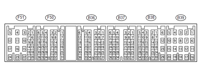
Use the illustration above as a reference for the ECM terminals.
|
Terminal No. (Symbol) |
Wiring Color |
Terminal Description |
Condition |
Specified Condition |
|---|---|---|---|---|
|
B37-2 (NSW) - B38-12 (E1) |
B - BR |
PNP switch signal |
|
Below 1 V |
|
11 to 14 V |
|||
|
B36-35 (P) - B38-12 (E1) |
L - BR |
P shift position switch signal |
|
11 to 14 V |
|
Below 1 V |
|||
|
B36-28 (R) - B38-12 (E1) |
R - BR |
R shift position switch signal |
|
11 to 14 V |
|
Below 1 V |
|||
|
B36-29 (N) - B38-12 (E1) |
G - BR |
N shift position switch signal |
|
11 to 14 V |
|
Below 1 V |
|||
|
B36-27 (D) - B38-12 (E1) |
B - BR |
D shift position switch signal |
|
11 to 14 V |
|
Below 1 V |
|||
|
F50-24 (S) - B38-12 (E1) |
V - BR |
S shift position switch signal |
|
11 to 14 V |
|
Below 1 V |
|||
|
F50-16 (SFTU) - B38-12 (E1) |
GR - BR |
Up-shift position switch signal |
|
11 to 14 V |
|
Below 1 V |
|||
|
F50-22 (SFTD) - B38-12 (E1) |
LG - BR |
Down-shift position switch signal |
|
11 to 14 V |
|
Below 1 V |
|||
|
B37-36 (S1) - B38-12 (E1) |
L-R - BR |
S1 solenoid signal |
Ignition switch ON |
11 to 14 V |
|
1st or 2nd gear |
11 to 14 V |
|||
|
3rd, 4th or 5th gear |
Below 1 V |
|||
|
B36-33 (S2) - B38-12 (E1) |
L-W - BR |
S2 solenoid signal |
Ignition switch ON |
Below 1 V |
|
2nd or 3rd gear |
11 to 14 V |
|||
|
1st, 4th or 5th gear |
Below 1 V |
|||
|
B36-31 (SR) - B38-12 (E1) |
G-W - BR |
SR solenoid signal |
Ignition switch ON |
Below 1 V |
|
5th gear |
11 to 14 V |
|||
|
1st gear |
Below 1 V |
|||
|
B38-33 (SL1+) - B38-32 (SL1-) |
V - R-B |
SL1 solenoid signal |
Engine idling |
Pulse generation (See waveform 1) |
|
B37-31 (SL2+) - B38-34 (SL2-) |
LG - P-L |
SL2 solenoid signal |
Engine idling |
Pulse generation (See waveform 2) |
|
B37-34 (SLT+) - B37-35 (SLT-) |
G-Y - L-B |
SLT solenoid signal |
Engine idling |
Pulse generation (See waveform 3) |
|
B37-33 (SLU+) - B37-32 (SLU-) |
G-R - Y-R |
SLU solenoid signal |
4th gear (lock-up) or 5th gear (lock-up) |
Pulse generation (See waveform 4) |
|
B38-5 (THO1) - B37-8 (ETHW) |
B-R - W-R |
No. 1 ATF temperature sensor signal |
No. 1 ATF temperature 115°C (239°F) or higher |
Below 1.5 V |
|
B38-11 (THO2) - B37-8 (ETHW) |
L-Y - W-R |
No. 2 ATF temperature sensor signal |
No. 2 ATF temperature 115°C (239°F) or higher |
Below 1.5 V |
|
B38-9 (SP2+) - B38-10 (SP2-) |
G - R |
Speed sensor SP2 signal |
Vehicle speed 20 km/h (12 mph) |
Pulse generation (See waveform 5) |
|
B38-3 (NT+) - B38-4 (NT-) |
B - Y |
Speed sensor NT signal |
Engine idling (shift lever in P or N) |
Pulse generation (See waveform 6) |
|
F50-32 (CANH) - B38-12 (E1) |
V - BR |
CAN communication line |
Ignition switch ON |
Pulse generation (See waveform 7) |
|
F50-31 (CANL) - B38-12 (E1) |
W - BR |
CAN communication line |
Ignition switch ON |
Pulse generation (See waveform 8) |
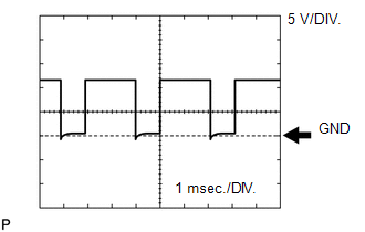
(a) Using an oscilloscope, check waveform 1.
 Reference
|
Terminal No. (Symbol) |
Tool Setting |
Condition |
|---|---|---|
|
B38-33 (SL1+) - B38-32 (SL1-) |
5 V/DIV., 1 msec./DIV. |
Engine idling |
(b) Using an oscilloscope, check waveform 2.
Reference
|
Terminal No. (Symbol) |
Tool Setting |
Condition |
|---|---|---|
|
B37-31 (SL2+) - B38-34 (SL2-) |
5 V/DIV., 1 msec./DIV. |
Engine idling |
(c) Using an oscilloscope, check waveform 3.
Reference
|
Terminal No. (Symbol) |
Tool Setting |
Condition |
|---|---|---|
|
B37-34 (SLT+) - B37-35 (SLT-) |
5 V/DIV., 1 msec./DIV. |
Engine idling |
(d) Using an oscilloscope, check waveform 4.
Reference
|
Terminal No. (Symbol) |
Tool Setting |
Condition |
|---|---|---|
|
B37-33 (SLU+) - B37-32 (SLU-) |
5 V/DIV., 1 msec./DIV. |
4th gear (lock-up) or 5th gear (lock-up) |
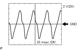
(e) Using an oscilloscope, check waveform 5.
 Reference
|
Terminal No. (Symbol) |
Tool Setting |
Condition |
|---|---|---|
|
B38-9 (SP2+) - B38-10 (SP2-) |
2 V/DIV., 20 msec./DIV. |
Vehicle speed 20 km/h (12 mph) |
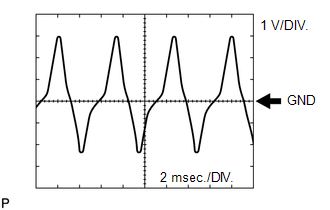
(f) Using an oscilloscope, check waveform 6.
 Reference
|
Terminal No. (Symbol) |
Tool Setting |
Condition |
|---|---|---|
|
B38-3 (NT+) - B38-4 (NT-) |
1 V/DIV., 2 msec./DIV. |
Engine idling (shift lever in P or N) |
(g) Using an oscilloscope, check waveform 7.
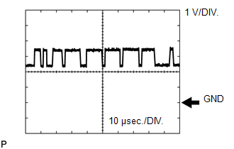 Reference
|
Terminal No. (Symbol) |
Tool Setting |
Condition |
|---|---|---|
|
F50-32 (CANH) - B38-12 (E1) |
1 V/DIV., 10 μsec./DIV. |
Ignition switch ON |
(h) Using an oscilloscope, check waveform 8.
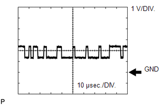 Reference
|
Terminal No. (Symbol) |
Tool Setting |
Condition |
|---|---|---|
|
F50-31 (CANL) - B38-12 (E1) |
1 V/DIV., 10 μsec./DIV. |
Ignition switch ON |
 Problem Symptoms Table
PROBLEM SYMPTOMS TABLE
HINT:
Use the table below to help determine the cause of problem symptoms.
If multiple suspected areas are listed, the potential causes of the symptoms
are lis ...
 Diagnosis System
DIAGNOSIS SYSTEM
1. DESCRIPTION
(a) When troubleshooting On-Board Diagnostic (OBD II) vehicles, the vehicle must
be connected to the OBD II scan tool (complying with SAE J1987). Various data outpu ...
Other materials about Toyota 4Runner:
Combination Meter ECU Communication Stop Mode
DESCRIPTION
Detection Item
Symptom
Trouble Area
Combination Meter ECU Communication Stop Mode
Either condition is met:
"Combination Meter" is not displayed on the "CAN B ...
Diagnosis System
DIAGNOSIS SYSTEM
1. DESCRIPTION
(a) Air conditioning system data and Diagnostic Trouble Codes (DTCs) can be read
through the Data Link Connector 3 (DLC3) of the vehicle. When the system seems to
be malfunctioning, use the Techstream to check for malfunct ...

0.0203