Toyota 4Runner: Diagnosis System
DIAGNOSIS SYSTEM
1. DESCRIPTION
(a) When troubleshooting On-Board Diagnostic (OBD II) vehicles, the vehicle must be connected to the OBD II scan tool (complying with SAE J1987). Various data output from the vehicle's ECM can then be read.
(b) OBD II regulations require that the vehicle's on-board computer illuminate the Malfunction Indicator Lamp (MIL) on the instrument panel when the computer detects a malfunction in:

(1) The emission control system/components
(2) The powertrain control components (which affect vehicle emissions)
(3) The computer
In addition, the applicable Diagnostic Trouble Codes (DTCs) prescribed by SAE J2012 are recorded in the ECM memory.
When the malfunction does not reoccur, the MIL stays illuminated until the ignition switch is turned off, and the MIL turns off when the engine is started. However, the DTCs remain recorded in the ECM memory.
(c) To check DTCs, connect the Techstream to the Data Link Connector 3 (DLC3) of the vehicle. The Techstream displays DTCs, freeze frame data and a variety of engine data.
The DTCs and freeze frame data can be cleared with the Techstream (See page
.gif) ).
).
2. NORMAL MODE AND CHECK MODE
(a) The diagnosis system operates in "normal mode" during normal vehicle use. In normal mode, "2 trip detection logic" is used to ensure accurate detection of malfunctions. "Check mode" is also available to technicians as an option. In check mode, "1 trip detection logic" is used for simulating malfunction symptoms and increasing the system's ability to detect malfunctions, including intermittent malfunctions.
3. 2 TRIP DETECTION LOGIC
(a) When a malfunction is first detected, the malfunction is temporarily stored in the ECM memory (1st trip). If the same malfunction is detected during the next drive cycle, the MIL is illuminated (2nd trip).
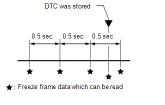
4. FREEZE FRAME DATA
(a) Freeze frame data records the engine conditions (fuel system data, calculated load, engine coolant temperature, fuel trim, engine speed, vehicle speed, etc.) when a malfunction is detected. When troubleshooting, freeze frame data can help determine if the vehicle was moving or stationary, if the engine was warmed up or not, if the air-fuel ratio was lean or rich, and other data from the time the malfunction occurred.
(b) The ECM records freeze frame data in 5 different instances: 1) 3 times before the DTC is stored, 2) once when the DTC is stored, and 3) once after the DTC is stored. These data can be used to simulate the vehicle condition around the time when the malfunction occurred. The data may be helpful in finding the cause of the malfunction, or determine if the DTC is being caused by a temporary malfunction or not.
5. CHECK DATA LINK CONNECTOR 3 (DLC3) (See page
)
6. CHECK MIL
(a) Check that the MIL illuminates when turning the ignition switch to ON.
If the MIL does not illuminate, there is a problem in the MIL circuit (See page
).
(b) When the engine is started, the MIL should turn off.
 Terminals Of Ecm
TERMINALS OF ECM
1. CHECK ECM
HINT:
The standard voltage at each ECM terminal is shown in the table below.
In the table, first follow the information under "Condition". Look under &quo ...
 Dtc Check / Clear
DTC CHECK / CLEAR
NOTICE:
When the diagnosis system is changed from normal mode to check mode or vice versa,
all DTCs and freeze frame data recorded in normal mode are cleared. Before changing
m ...
Other materials about Toyota 4Runner:
Antenna Coil Open / Short (B2784)
DESCRIPTION
The antenna coil receives key code signals from the transponder chip in the key
grip. The coil is built into the transponder key amplifier, which amplifies the
key code signals and outputs the signals to the transponder key ECU assembly.
This ...
Selecting a play mode
Press
(BROWSE) to select iPod menu mode.
Press
,
,
or
as corresponds to the desired play
mode.
Pressing (MORE) to change to
the second selection list.
Play mode list
Depending on the model, the name of your iPod may be displayed at the top ...

0.0163