Toyota 4Runner: Terminals Of Ecu
TERMINALS OF ECU
1. CHECK AIR CONDITIONING AMPLIFIER ASSEMBLY
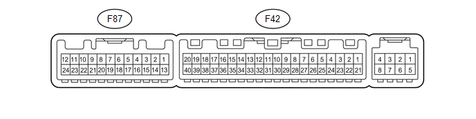
(a) Disconnect the F42 air conditioning amplifier connector.
(b) Measure the voltage and resistance according to the value(s) in the table below.
|
Terminal No. (Symbol) |
Wiring Color |
Terminal Description |
Condition |
Specified Condition |
|---|---|---|---|---|
|
F42-21 (B) - F42-14 (GND) |
V - W-B |
Battery power source |
Always |
11 to 14 V |
|
F42-1 (IG+) - F42-14 (GND) |
L - W-B |
Ignition power supply |
Ignition switch ON |
11 to 14 V |
|
F42-1 (IG+) - F42-14 (GND) |
L - W-B |
Ignition power supply |
Ignition switch off |
Below 1 V |
|
F42-14 (GND) - Body ground |
W-B - Body ground |
Ground |
Always |
Below 1 Ω |
- If the result is not as specified, there may be a malfunction on the wire harness side.
(c) Reconnect the F42 air conditioning amplifier connectors.
(d) Measure the voltage and resistance according to the value(s) in the table below.
|
Terminal No. (Symbol) |
Wiring Color |
Terminal Description |
Condition |
Specified Condition |
|---|---|---|---|---|
|
F42-40 (FDEF) - Body ground |
LG - Body ground |
Windshield deicer relay operation signal |
Ignition switch ON, outer mirror heater switch off |
11 to 14 V |
|
F42-40 (FDEF) - Body ground |
LG - Body ground |
Windshield deicer relay operation signal |
Ignition switch ON, outer mirror heater switch on |
Below 1 V |
|
F87-11 (FDF1) - Body ground |
P - Body ground |
Outer mirror heater switch indicator signal output |
Ignition switch ON, outer mirror heater switch off |
11 to 14 V |
|
F87-11 (FDF1) - Body ground |
P - Body ground |
Outer mirror heater switch indicator signal output |
Ignition switch ON, outer mirror heater switch on |
Below 1 V |
|
F87-5 (SW 1) - Body ground |
R - Body ground |
Outer mirror heater switch signal input |
Ignition switch ON, outer mirror heater switch off |
Below 1 V |
|
F87-5 (SW 1) - Body ground |
R - Body ground |
Outer mirror heater switch signal input |
Ignition switch ON, outer mirror heater switch on |
11 to 14 V |
- If the result is not as specified, the air conditioning amplifier assembly may have a malfunction.
 Problem Symptoms Table
PROBLEM SYMPTOMS TABLE
HINT:
Use the table below to help determine the cause of problem symptoms.
If multiple suspected areas are listed, the potential causes of the symptoms
are lis ...
 Windshield Glass
...
Other materials about Toyota 4Runner:
Reassembly
REASSEMBLY
PROCEDURE
1. INSTALL NAVIGATION ANTENNA ASSEMBLY (w/ Navigation System)
2. INSTALL AUTOMATIC LIGHT CONTROL SENSOR
3. INSTALL INSTRUMENT PANEL PASSENGER AIRBAG ASSEMBLY
4. INSTALL NO. 2 INSTRUMENT PANEL WIRE
(a) Attach the 17 clamps to ...
Active traction control system
The active traction control system automatically helps prevent the
spinning of 4 wheels when the vehicle is started or accelerated on slippery road
surfaces.
System operation
Part-time 4WD models:
Stop the vehicle, shift the shift lever to N and shift ...

0.0103