Toyota 4Runner: Terminals Of Ecu
TERMINALS OF ECU
1. CHECK NO. 1 AIR CONDITIONING AMPLIFIER ASSEMBLY
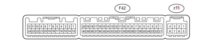
(a) Disconnect the F42 No. 1 air conditioning amplifier assembly connector.
(b) Measure the voltage and resistance according to the value(s) in the table below.
|
Terminal No. (Symbol) |
Wiring Color |
Terminal Description |
Condition |
Specified Condition |
|---|---|---|---|---|
|
F42-21 (B) - F42-14 (GND) |
V - W-B |
Battery power source |
Always |
11 to 14 V |
|
F42-1 (IG+) - F42-14 (GND) |
L - W-B |
Ignition power supply |
Ignition switch ON |
11 to 14 V |
|
Ignition switch off |
Below 1 V |
|||
|
F42-14 (GND) - Body ground |
W-B - Body ground |
Ground for main power supply |
Always |
Below 1 Ω |
- If the result is not as specified, there may be a malfunction on the wire harness side.
(c) Reconnect the F42 No. 1 air conditioning amplifier assembly connector.
(d) Measure the voltage according to the value(s) in the table below.
|
Terminal No. (Symbol) |
Wiring Color |
Terminal Description |
Condition |
Specified Condition |
|---|---|---|---|---|
|
F42-3 (PTC1) - Body ground |
V - Body ground |
PTC NO. 1 relay operation signal |
|
11 to 14 V* |
|
F42-4 (PTC3) - Body ground |
P - Body ground |
PTC NO. 3 relay operation signal |
|
11 to 14 V* |
|
F42-5 (TAM) - F42-13 (SG-2) |
V - G |
Cooler thermistor (ambient temperature sensor) signal |
|
1.35 to 1.75 V |
|
F42-5 (TAM) - F42-13 (SG-2) |
V - G |
Cooler thermistor (ambient temperature sensor) signal |
|
0.9 to 1.2 V |
|
F42-8 (LOCK) - F42-13 (SG-2) |
R - G |
A/C compressor lock sensor signal |
|
Pulse generation (See waveform 1) |
|
F42-9 (PRE) - Body Ground |
G - Body Ground |
No. 1 pressure switch signal |
|
Below 1 V |
|
F42-9 (PRE) - Body Ground |
G - Body Ground |
No. 1 pressure switch signal |
|
4.69 V or higher |
|
F42-17 (AC1) - F42-14 (GND) |
LG - W-B |
Compressor operation signal |
|
Below 1 V |
|
F42-18 (MHTR) - F42-14 (GND) |
G - W-B |
MIR HTR relay signal |
|
Below 1 V |
|
F42-20 (MGC) - F42-14 (GND) |
R - W-B |
Magnet clutch assembly operation signal |
|
Below 1 V |
|
F42-22 (PTC2) - Body ground |
LG - Body ground |
PTC NO. 2 relay operation signal |
|
11 to 14 V* |
|
F42-23 (BLW) - F42-14 (GND) |
LG - W-B |
Blower with fan motor sub-assembly control signal |
|
Pulse generation (See waveform 2) |
|
F42-25 (ALT) - F42-14 (GND) |
L - W-B |
Generator signal (PTC heater control) |
Engine started |
Pulse generation |
|
F42-27 (ACT) - F42-14 (GND) |
SB - W-B |
Compressor operation signal |
|
4.75 to 5.25 V |
|
F42-29 (TR) - F42-34 (SG-1) |
GR - SB |
Cooler thermistor (room temperature sensor) signal |
|
1.8 to 2.2 V |
|
1.2 to 1.6 V |
|||
|
F42-32 (TSP) - F42-14 (GND) |
B - W-B |
Automatic light control sensor (solar sensor) power signal (for front passenger side) |
|
0.8 to 4.3 V |
|
Below 0.8 V |
|||
|
F42-33 (TSD) - F42-14 (GND) |
GR - W-B |
Automatic light control sensor (solar sensor) power signal (for driver side) |
|
0.8 to 4.3 V |
|
Below 0.8 V |
|||
|
z15-2 (BUS G) - Body ground |
- |
Ground for BUS IC |
Always |
Below 1 V |
|
z15-3 (BUS) - z15-2 (BUS G) |
- |
BUS IC control signal |
Ignition switch ON |
Pulse generation |
|
z15-4 (B BUS) - z15-2 (BUS G) |
- |
Power supply for BUS IC |
Always |
11 to 14 V |
|
z15-6 (TE) - z15-5 (SG-3) |
- |
No. 1 cooler thermistor signal |
|
1.7 to 2.1 V |
|
0.9 to 1.3 V |
HINT:
*: After the measurement conditions are met, wait 30 seconds before performing measurements.
- If the result is not as specified, the No. 1 air conditioning amplifier assembly may have a malfunction.
(e) Using an oscilloscope, check waveform 1.
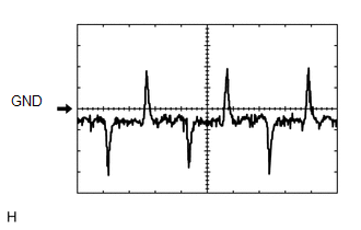 A/C Compressor Lock Sensor Signal
|
Item |
Content |
|---|---|
|
Terminal No. (Symbol) |
F42-8 (LOCK) - F42-13 (SG-2) |
|
Tool Setting |
200 mV/DIV., 10 ms./DIV. |
|
Condition |
|
(f) Using an oscilloscope, check waveform 2.
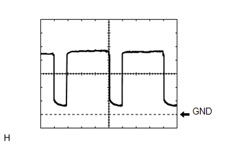 Blower Motor Control Signal
|
Item |
Content |
|---|---|
|
Terminal No. (Symbol) |
F42-23 (BLW) - F42-14 (GND) |
|
Tool Setting |
1 V/DIV., 500 μs/DIV. |
|
Condition |
|
HINT:
When the blower level is increased, the duty ratio changes accordingly.
2. CHECK HEATER CONTROL

(a) Disconnect the F29 heater control connector.
(b) Measure the voltage and resistance according to the value(s) in the table below.
|
Terminal No. (Symbol) |
Wiring Color |
Terminal Description |
Condition |
Specified Condition |
|---|---|---|---|---|
|
F29-4 (IG+) - F29-11 (GND) |
L - W-B |
IG power supply |
Ignition switch ON |
11 to 14 V |
|
F29-11 (GND) - Body ground |
W-B - Body ground |
Ground |
Always |
Below 1 Ω |
If the result is not as specified, there may be a malfunction on the wire harness side.
3. CHECK DRIVER SIDE JUNCTION BLOCK ASSEMBLY AND MAIN BODY ECU (MULTIPLEX NETWORK BODY ECU)
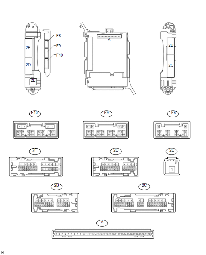
(a) Remove the main body ECU (See page .gif) ).
).
(b) Measure the voltage and resistance according to the value(s) in the table below.
|
Terminal No. (Symbol) |
Wiring Color |
Terminal Description |
Condition |
Specified Condition |
|---|---|---|---|---|
|
A-11 (GND1) - Body ground |
- |
Ground |
Always |
Below 1 Ω |
|
A-29 (ACC) - Body ground |
- |
ACC power supply |
Ignition switch ACC |
11 to 14 V |
|
A-31 (ALTB) - Body ground |
- |
Battery power supply |
Always |
11 to 14 V |
|
A-32 (IG) - Body ground |
- |
Ignition switch power supply |
Ignition switch ON |
11 to 14 V |
If the result is not as specified, there may be a malfunction in the wire harness.
(c) Install the main body ECU (See page ).
(d) Measure the voltage and resistance according to the value(s) in the table below.
|
Terminal No. (Symbol) |
Wiring Color |
Terminal Description |
Condition |
Specified Condition |
|---|---|---|---|---|
|
F9-20 (CLTB) - Body ground |
P - Body ground |
Automatic light control sensor power supply output |
Ignition switch off |
Below 1 V |
|
Ignition switch ON |
11 to 14 V |
|||
|
F9-22 (CLTE) - Body ground |
L - Body ground |
Automatic light control sensor ground |
Always |
Below 1 Ω |
If the result is not as specified, the main body ECU or driver side junction block assembly may have a malfunction.
 Problem Symptoms Table
PROBLEM SYMPTOMS TABLE
HINT:
Use the table below to help determine the cause of problem symptoms.
If multiple suspected areas are listed, the potential causes of the symptoms
are lis ...
 Diagnosis System
DIAGNOSIS SYSTEM
1. DESCRIPTION
(a) Air conditioning system data and Diagnostic Trouble Codes (DTCs) can be read
through the Data Link Connector 3 (DLC3) of the vehicle. When the system seems to
...
Other materials about Toyota 4Runner:
Garage door opener
The garage door opener can be programmed to operate garage doors, gates,
entry doors, door locks, home lighting systems, security systems, and other
devices.
The garage door opener (HomeLink® Universal Transceiver) is manufactured
under license from Ho ...
Operation Check
OPERATION CHECK
1. CHECK KEY REMINDER WARNING SYSTEM
(a) Check that the key reminder warning buzzer sounds.
(1) With the driver side door closed, insert the key into the ignition key cylinder
and leave the ignition switch off, or turn the ignition switch ...

0.028