Toyota 4Runner: Diagnosis System
DIAGNOSIS SYSTEM
1. DESCRIPTION
(a) Air conditioning system data and Diagnostic Trouble Codes (DTCs) can be read through the Data Link Connector 3 (DLC3) of the vehicle. When the system seems to be malfunctioning, use the Techstream to check for malfunctions and perform troubleshooting.
2. CHECK DLC3
(a) Check the DLC3 (See page .gif) ).
).
3. LIST OF OPERATION METHODS
(a) By operating each of the air conditioning control switches as shown in the diagram below, it is possible to enter the diagnostic check mode.
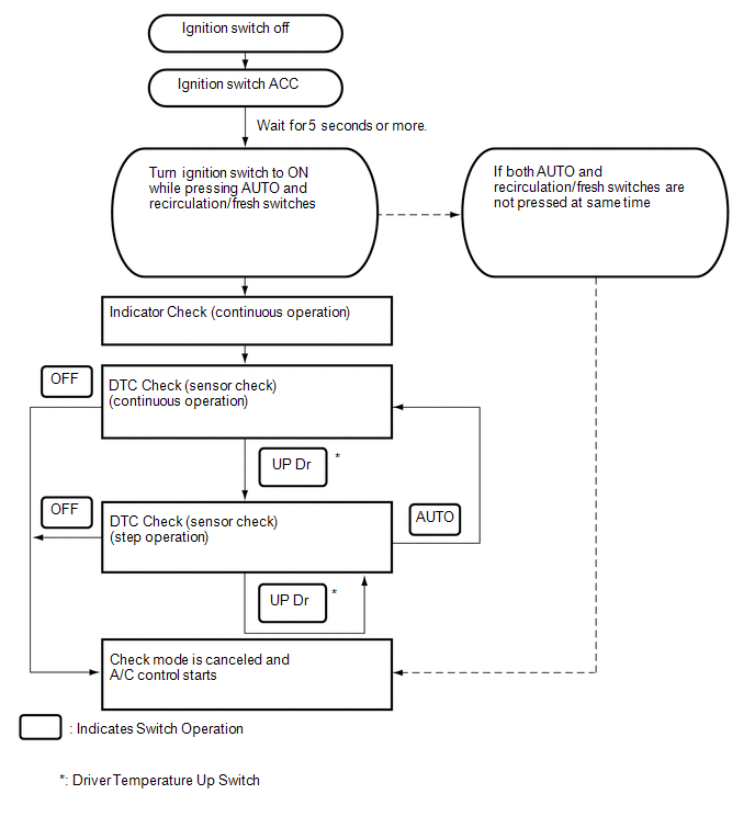
4. INDICATOR CHECK
(a) Turn the ignition switch off.
(b) Turn the ignition switch to ACC and wait at least 5 seconds.
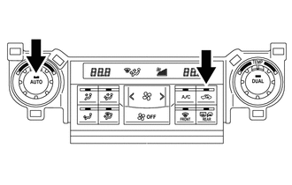
(c) Press and hold the air conditioning control "AUTO" switch and "recirculation/fresh" switch simultaneously, and turn the ignition switch to ON. Continue holding the 2 switches until panel diagnosis mode begins.
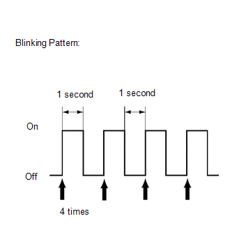
(d) Check that all indicators turn on and off 4 times in succession at 1 second intervals.
HINT:
- After the indicator check is completed, the system enters DTC check mode automatically.
- Press the "OFF" switch to cancel the check mode.
5. DTC CHECK (SENSOR CHECK)
(a) Start the engine and warm it up.
(b) Perform the indicator check.
HINT:
After the indicator check is completed, the system enters DTC check mode automatically.
(c) Read the code displayed on the panel.
NOTICE:
In sensor check mode, which is automatically entered after indicator check mode, troubleshooting may be only partially completed.
HINT:
Refer to the Diagnostic Trouble Code Chart for details of the codes (See page
).
- When there are no problems, DTC 00 is output.
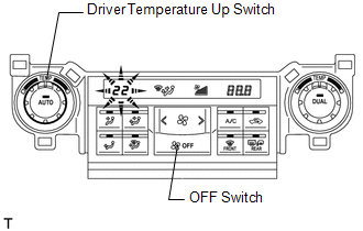
- As an example, the illustration shows that DTC 22 is output.
(d) If the codes are difficult to read because they change automatically, operate the driver temperature up switch to display the codes one at a time so that they can be read easily. The items are displayed one by one each time the driver temperature up switch is operated.
HINT:
Push the "OFF" switch to finish panel diagnosis.
 Terminals Of Ecu
TERMINALS OF ECU
1. CHECK NO. 1 AIR CONDITIONING AMPLIFIER ASSEMBLY
(a) Disconnect the F42 No. 1 air conditioning amplifier assembly connector.
(b) Measure the voltage and resistance according to ...
 Data List / Active Test
DATA LIST / ACTIVE TEST
1. DATA LIST
HINT:
Using the Techstream to read the Data List allows the values or states of switches,
sensors, actuators and other items to be read without removing any p ...
Other materials about Toyota 4Runner:
Abnormal Temperature Inside ID1 Tire (C2165/65-C2169/69)
DESCRIPTION
Each tire pressure warning valve and transmitter measures the internal temperature
of its tire as well as the tire pressure and transmits the information to the tire
pressure warning ECU along with the transmitter ID. If the measured temperatu ...
Reverse Signal Circuit
DESCRIPTION
The radio and display receiver assembly receives a reverse signal from the park/neutral
position switch assembly.
WIRING DIAGRAM
PROCEDURE
1.
CHECK HARNESS AND CONNECTOR (REVERSE SIGNAL)
(a) Disconnect the G ...

0.0074