Toyota 4Runner: Terminals Of Ecu
TERMINALS OF ECU
1. CHECK FRONT POWER SEAT SWITCH LH

(a) Disconnect the b18 and b19 connectors from the front power seat switch LH.
(b) Measure the voltage and resistance according to the value(s) in the table below.
|
Terminal No. (Symbol) |
Wiring Color |
Terminal Description |
Condition |
Specified Condition |
|---|---|---|---|---|
|
b18-2 (GND1) - Body ground |
W-B - Body ground |
Ground |
Always |
Below 1 Ω |
|
b18-7 (+B1) - b18-2 (GND1) |
W - W-B |
Power source |
Always |
11 to 14 V |
|
b19-12 (SYSB) - b18-2 (GND1) |
P - W-B |
System power source |
Always |
11 to 14 V |
If the result is not as specified, there may be a malfunction on the wire harness side.
(c) Reconnect the b18 and b19 switch connectors.
(d) Measure the voltage according to the value(s) in the table below.
|
Terminal No. (Symbol) |
Wiring Color |
Terminal Description |
Condition |
Specified Condition |
|---|---|---|---|---|
|
b18-3 (SLD+) - b18-2 (GND1) |
L - W-B |
Sliding motor signal (forward) |
Slide switch off |
Below 1 V |
|
Slide switch on (Forward) |
11 to 14 V |
|||
|
b18-4 (SLD-) - b18-2 (GND1) |
GR - W-B |
Sliding motor signal (rearward) |
Slide switch off |
Below 1 V |
|
Slide switch on (Rearward) |
11 to 14 V |
|||
|
b18-5 (FRV-) - b18-2 (GND1) |
R - W-B |
Front vertical motor signal (downward) |
Front vertical switch off |
Below 1 V |
|
Front vertical switch on (Downward) |
11 to 14 V |
|||
|
b18-6 (+B2) - b18-1 (GND2) |
SB - W-B |
Power source |
Always |
11 to 14 V |
|
b18-8 (FRV+) - b18-2 (GND1) |
B - W-B |
Front vertical motor signal (upward) |
Front vertical switch off |
Below 1 V |
|
Front vertical switch on (Upward) |
11 to 14 V |
|||
|
b18-9 (RCL+) - b18-2 (GND1) |
P - W-B |
Reclining motor signal (forward) |
Reclining switch off |
Below 1 V |
|
Reclining switch on (Forward) |
11 to 14 V |
|||
|
b18-11 (RCL-) - b18-2 (GND1) |
LG - W-B |
Reclining motor signal (rearward) |
Reclining switch off |
Below 1 V |
|
Reclining switch on (Rearward) |
11 to 14 V |
|||
|
b18-10 (LFT+) - b18-2 (GND1) |
V - W-B |
Lifter motor signal (upward) |
Lifter switch off |
Below 1 V |
|
Lifter switch on (Upward) |
11 to 14 V |
|||
|
b18-12 (LFT-) - b18-2 (GND1) |
G - W-B |
Lifter motor signal (downward) |
Lifter switch off |
Below 1 V |
|
Lifter switch on (Downward) |
11 to 14 V |
|||
|
b19-1 (SGND) - b18-2 (GND1) |
BR - W-B |
Ground |
Always |
Below 1 Ω |
|
b19-3 (SSFV) - b19-1 (SGND) |
R - BR |
Front vertical position signal |
Front vertical function operating |
4.5 to 4.8 V |
|
b19-4 (SSRL) - b19-1 (SGND) |
P - BR |
Lifter position signal |
Lifter function operating |
4.5 to 4.8 V |
|
b19-5 (SSRS) - b19-1 (SGND) |
G- BR |
Slide position signal |
Slide function operating |
4.5 to 4.8 V |
|
b19-11 (SSRR) - b19-1 (SGND) |
V - BR |
Reclining position signal |
Reclining function operating |
4.5 to 4.8 V |
If the result is not as specified, the front power seat switch LH may have a malfunction.
2. CHECK DRIVER SIDE JUNCTION BLOCK ASSEMBLY AND MAIN BODY ECU (MULTIPLEX NETWORK BODY ECU)
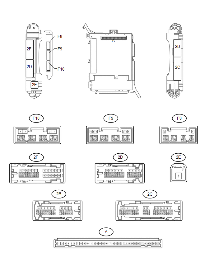
(a) Remove the main body ECU (multiplex network body ECU) (See page
.gif) ).
).
(b) Measure the voltage and resistance according to the value(s) in the table below.
|
Terminal No. (Symbol) |
Wiring Color |
Terminal Description |
Condition |
Specified Condition |
|---|---|---|---|---|
|
A-30 (BECU) - Body ground |
- |
Power source |
Always |
11 to 14 V |
|
A-32 (IG) - Body ground |
- |
Power source (IG) |
Engine switch on (IG) |
11 to 14 V |
|
Engine switch off |
Below 1 V |
|||
|
A-11 (GND1) - Body ground |
- |
Ground |
Always |
Below 1 Ω |
|
F10-3 (GND2) - Body ground |
W-B - Body ground |
Ground |
Always |
Below 1 Ω |
If the result is not as specified, there may be a malfunction on the wire harness side.
 Problem Symptoms Table
PROBLEM SYMPTOMS TABLE
HINT:
Use the table below to help determine the cause of problem symptoms.
If multiple suspected areas are listed, the potential causes of the symptoms
are lis ...
 Data List / Active Test
DATA LIST / ACTIVE TEST
1. DATA LIST
HINT:
Using the Techstream to read the Data List allows the values or states of switches,
sensors, actuators and other items to be read without removing any p ...
Other materials about Toyota 4Runner:
Antenna location and effective range
Antenna location
1. Antennas outside the cabin
2. Antennas inside the cabin
3. Antenna outside the luggage compartment
Effective range (areas within which the electronic key is detected)
When locking or unlocking the
doors
The system can be opera ...
Adjustment
ADJUSTMENT
CAUTION / NOTICE / HINT
HINT:
Use the same procedure for the RH and LH sides.
The procedure listed below is for the LH side.
PROCEDURE
1. VEHICLE PREPARATION FOR HEADLIGHT AIMING ADJUSTMENT
(a) Prepare the vehicle:
Ma ...

0.011