Toyota 4Runner: Terminals Of Ecu
TERMINALS OF ECU
1. CHECK DCM (TELEMATICS TRANSCEIVER)
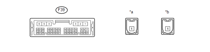 Text in Illustration
|
*a |
Connector color: Blue (to Telephone antenna) |
*b |
Connector color: Gray (to GPS antenna) |
|
Terminal No. (Symbol) |
Wiring Color |
Terminal Description |
Condition |
Specified Condition |
|---|---|---|---|---|
|
F39-1 (+B) - F39-4 (E) |
P - W-B |
Vehicle battery power supply |
Always |
11 to 14 V |
|
F39-2 (SPI+) - F39-4 (E) |
V - W-B |
Sound signal |
Audio system playing |
Waveform synchronized with sound is input |
|
F39-3 (SPI-) - F39-4 (E) |
P - W-B |
Sound signal |
Audio system playing |
Waveform synchronized with sound is input |
|
F39-4 (E) - Body ground |
W-B - Body ground |
Ground |
Always |
Below 1 V |
|
F39-5 (SPO+) - F39-4 (E) |
LG - W-B |
Sound signal |
Audio system playing, or emergency call mode on |
Waveform synchronized with sound is output |
|
F39-6 (SPO-) - F39-4 (E) |
L - W-B |
Sound signal |
Audio system playing, or emergency call mode on |
Waveform synchronized with sound is output |
|
F39-7 (IG2) - F39-4 (E) |
W - W-B |
IG power supply |
Ignition switch ON |
11 to 14 V |
|
Ignition switch off |
Below 1 V |
|||
|
F39-8 (ACC) - F39-4 (E) |
P - W-B |
ACC power supply |
Ignition switch ACC |
11 to 14 V |
|
Ignition switch off |
Below 1 V |
|||
|
F39-10 (SPDP) - F39-4 (E) |
SB - W-B |
Vehicle speed signal |
See "Vehicle Signal Check Mode" (See page
|
- |
|
F39-11 (IND1) - F39-4 (E) |
R - W-B |
Manual (SOS) switch red indicator illumination signal |
Illuminates for 2 seconds after turning the ignition switch ON |
1 to 8.5 V |
|
Ignition switch off |
Below 1 V |
|||
|
F39-12 (IND2) - F39-4 (E) |
V - W-B |
Manual (SOS) switch green indicator illumination signal |
Illuminates for 2 seconds after turning the ignition switch ON |
1 to 8.5 V |
|
Ignition switch off |
Below 1 V |
|||
|
F39-13 (BBI-) |
G |
BUB (Back-Up Battery) power supply |
- |
- |
|
F39-17 (MUTE) - F39-4 (E) |
L - W-B |
Mute signal |
Audio system playing |
3.5 V or higher |
|
Emergency call mode on |
Below 1 V |
|||
|
F39-18 (MCO+) - F39-4 (E) |
B - W-B |
Microphone voice signal |
See "Microphone & Voice Recognition Check" (See page
|
- |
|
F39-19 (MCO-) - F39-4 (E) |
W - W-B |
Microphone voice signal |
See "Microphone & Voice Recognition Check" (See page
|
- |
|
F39-20 (CTR1) |
L |
BUB (Back-Up Battery) control line |
- |
- |
|
F39-21 (CTR2) |
GR |
BUB (Back-Up Battery) control line |
- |
- |
|
F39-23 (ILL+) - F39-4 (E) |
G - W-B |
Illumination signal |
Light control switch off |
Below 1 V |
|
Light control switch tail or on |
11 to 14 V |
|||
|
F39-24 (GSW) - F39-4 (E) |
B - W-B |
Collision detection signal |
Ignition switch ON |
Pulse generation (See waveform 1) |
|
F39-25 (SIL) |
G |
Serial communication signal |
- |
- |
|
F39-26 (SIG-) - F39-4 (E) |
LG - W-B |
Ground |
Always |
Below 1 V |
|
F39-27 (SIG1) - F39-4 (E) |
P - W-B |
Manual (SOS) switch condition signal |
Manual (SOS) switch not pressed |
1.4 to 1.8 V |
|
Manual (SOS) switch pressed |
0.5 to 0.9 V |
|||
|
F39-30 (BBI+) |
LG |
BUB (Back-Up Battery) power supply |
- |
- |
|
F39-32 (SGND) - F39-4 (E) |
Shielded - W-B |
Shield ground |
Always |
Below 1 V |
|
F39-33 (MCVD) - F39-4 (E) |
R - W-B |
Telephone microphone assembly power supply |
Ignition switch off |
Below 1 V |
|
Ignition switch ON |
4 to 6 V |
|||
|
F39-34 (MCI+) - F39-4 (E) |
B - W-B |
Microphone voice signal |
See "Microphone & Voice Recognition Check" (See page
|
- |
|
F39-35 (MCI-) - F39-4 (E) |
W - W-B |
Microphone voice signal |
See "Microphone & Voice Recognition Check" (See page
|
- |
.gif) )
)(a) Oscilloscope waveform:
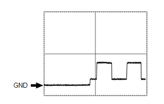
(1) Waveform 1
|
Item |
Condition |
|---|---|
|
Tester connection |
F39-24 (GSW) - F39-4 (E) |
|
Tool setting |
5.0 V/DIV., 20 ms/DIV. |
|
Vehicle condition |
Ignition switch ON |
 Problem Symptoms Table
PROBLEM SYMPTOMS TABLE
HINT:
Use the table below to help determine the cause of problem symptoms.
If multiple suspected areas are listed, the potential causes of the symptoms
are lis ...
 Diagnosis System
DIAGNOSIS SYSTEM
1. CHECK DLC3
(a) Check the DLC3 (See page ).
2. CHECK INDICATOR
(a) When a malfunction is detected in the Safety Connect system, the manual (SOS)
switch red indicator on the m ...
Other materials about Toyota 4Runner:
Operating the lights and wipers
Headlight switch
The headlights can be operated manually or automatically.
Turning the end of the lever turns on the lights as follows:
Type A
1. The daytime running lights
turn on.
2. The side marker,
parking, tail, license plate, daytime r ...
Telephone Microphone
Components
COMPONENTS
ILLUSTRATION
ILLUSTRATION
Removal
REMOVAL
PROCEDURE
1. REMOVE DRIVE MONITOR SWITCH
2. REMOVE MAP LIGHT ASSEMBLY
3. REMOVE TELEPHONE MICROPHONE ASSEMBLY
(a) Disconnect the 6 connectors.
...

0.0259