Toyota 4Runner: Test Mode Procedure
TEST MODE PROCEDURE
NOTICE:
- After replacing the master cylinder solenoid and/or yaw rate and acceleration sensor, perform calibration.
- VSC is prohibited during test mode.
HINT:
- By switching the skid control ECU from normal mode to test mode, abnormality detection sensitivity is enhanced and troubleshooting can be conducted efficiently.
- Perform a sensor check in test mode after the speed sensor or sensor rotor has been repaired or replaced.
- If the ignition switch is turned from ON to ACC or off during test mode, DTCs related to the signal check function will not be cleared. During test mode, do not change to normal mode.
- During test mode, the skid control ECU stores all DTCs related to the signal check function, and the DTCs are cleared if normality is confirmed. Any remaining DTCs indicate abnormalities that were found.
1. TEST MODE (SIGNAL CHECK) PROCEDURE
(a) When using the Techstream:
(1) Place the vehicle on a level surface with an inclination of less than 1%.
(2) Turn the ignition switch off.
(3) Check that the shift lever is in P.
(4) Connect the Techstream to the DLC3.
(5) Turn the ignition switch to ON.
(6) Turn the Techstream on.
(7) Enter the following menus: Chassis / ABS/VSC/ TRAC / Utility / Signal Check.
(8) Check that the ABS warning light and slip indicator light blink at 0.126 second intervals (0.126 seconds on and 0.126 seconds off).
(9) Start the engine.
(b) When using SST check wire:
(1) Place the vehicle on a level surface with an inclination of less than 1%.
(2) Turn the ignition switch off.
(3) Check that the shift lever is in P.
(4) Using SST, connect terminals 12 (TS) and 4 (CG) of the DLC3.
SST: 09843-18040
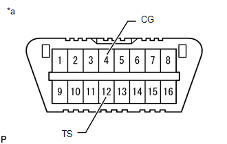 Text in Illustration
|
*a |
Front view of DLC3 |
(5) Turn the ignition switch to ON.
(6) Check that the ABS warning light and slip indicator light blink at 0.126 second intervals (0.126 seconds on and 0.126 seconds off).
(7) Start the engine.
(c) ABS Signal Check
HINT:
Check that the ABS warning light is blinking in the test mode blinking pattern before performing the ABS signal check.
(d) Master Cylinder Pressure Sensor and Acceleration Sensor Check
(1) Keep the vehicle stationary on a level surface for 1 second or more.
(2) With the vehicle stationary, release the brake pedal for 1 second or more, and then quickly depress the brake pedal with a force of 98 N (10 kgf, 22 lbf) or more for 1 second.
(3) Check that the ABS warning light comes on for 3 seconds.
HINT:
During test mode, the ABS warning light will turn on for 3 seconds every time the above operation is performed.
(e) 4WD Detection Switch Check (for Part-time 4WD)
(1) Move the transfer shift lever or transfer position switch to H4 to put the vehicle into four-wheel drive.
HINT:
Move the vehicle either forward or backward a little to engage 4WD.
(2) Move the transfer shift lever or transfer position switch to H2 to put the vehicle into two-wheel drive.
(f) Center Differential Lock Detection Switch Check (for Full-time 4WD)
(1) Set the transfer position switch to the H4L position to lock the center differential.
HINT:
Move the vehicle either forward or backward a little to lock the center differential.
(2) Set the transfer position switch to the H4F position to unlock the center differential.
(g) Speed Sensor Check
NOTICE:
- Before performing the speed sensor signal check, complete the master cylinder pressure sensor checks.
- The signal check may not be completed if the wheels of the vehicle spin or the steering wheel is turned during this check.
(1) Drive the vehicle straight forward at a speed of 90 km/h (60 mph) or more for several seconds (forward signal check).
(2) Check that the ABS warning light goes off.
(3) Drive the vehicle in reverse for more than 1 second at 3 km/h (2 mph) or more (reverse signal check).
(4) Check that the ABS warning light goes off.
HINT:
Drive the vehicle in reverse and check the speed sensor signal. Note that the signal check cannot be completed if the vehicle speed is 45 km/h (28 mph) or more.
NOTICE:
- The sensor check may not be completed if wheelspin occurs.
- The ABS warning light blinks when the sensor check has been completed and the brake pedal is depressed.
- The ABS warning light comes on immediately after a malfunction has been detected during the speed sensor check.
(5) Stop the vehicle.
NOTICE:
- The speed sensor signal check may not be completed if the speed sensor signal check is started while turning the steering wheel or spinning the wheels.
- If the signal check is not been completed, the ABS warning light blinks while driving and the ABS does not operate.
HINT:
When the signal check is completed, the ABS warning light goes off while driving and blinks in the test mode pattern while stationary.
(h) VSC Signal Check
HINT:
Check that the slip indicator light is blinking in the test mode blinking pattern (0.126 seconds on and 0.126 seconds off) before performing the VSC signal check.
(i) Downhill Assist Control Switch Check (w/ Downhill Assist Control)
(1) Push the downhill assist control switch and check that the downhill assist control indicator light is blinking.
(2) Turn the downhill assist control switch off.
(j) Crawl Switch Check (w/ Crawl Control)
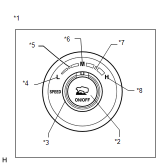 Text in Illustration
|
*1 |
Crawl Control Switch |
|
*2 |
ON/OFF Switch |
|
*3 |
Speed Selector Switch |
|
*4 |
Low |
|
*5 |
Medium-low |
|
*6 |
Medium |
|
*7 |
Medium-high |
|
*8 |
High |
(1) Push the crawl ON/OFF switch and check that the crawl indicator light is on while the switch is being pushed.
(2) Turn the crawl ON/OFF switch off.
(3) Turn the speed selector switch to L (low).
(4) Turn the speed selector switch to medium-low.
(5) Turn the speed selector switch to M (medium).
(6) Turn the speed selector switch to medium-high.
(7) Turn the speed selector switch to H (high).
(8) Turn the speed selector switch to L (low).
(k) VSC OFF Switch Check (for 2WD)
(1) Press the VSC OFF switch.
(2) Check that the AUTO LSD indicator light and VSC OFF indicator light come on.
(3) Press the VSC OFF switch again to turn the AUTO LSD indicator light and VSC OFF indicator light off.
(l) VSC OFF Switch Check (for 4WD)
(1) Press the VSC OFF switch.
(2) Check that the VSC OFF indicator light comes on.
(3) Press the VSC OFF switch again to turn the VSC OFF indicator off.
(m) End of Signal Check
(1) If the signal check is completed, the ABS warning light blinks (0.126 seconds on and 0.126 seconds off) when the vehicle is stopped and goes off while driving the vehicle.
NOTICE:
If the signal check has not been completed, the ABS warning light blinks while driving and the ABS does not operate.
(n) Read test mode (signal check) DTCs (when using the Techstream)
(1) Read the DTC(s) by following the Techstream screen.
NOTICE:
- If only DTCs other than test mode sensor check DTCs are output, repair the malfunctions and clear the DTCs.
- If test mode sensor check DTCs and other DTCs are output or if only test mode sensor check DTCs are output, repair the malfunctions, clear the DTCs, and perform the test mode inspection again.
HINT:
Refer to Signal Check DTCs.
(2) Turn the ignition switch off and disconnect the Techstream.
(o) Read test mode (signal check) DTCs (when using SST check wire)
(1) Using SST, connect terminals 13 (TC), 12 (TS) and 4 (CG) of the DLC3.
SST: 09843-18040
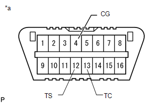 Text in Illustration
|
*a |
Front view of DLC3 |
(2) Read the number of blinks of the ABS warning light and slip indicator light.
HINT:
- If every sensor is normal, the normal code is output (a cycle of 0.25 seconds on and 0.25 seconds off is repeated).
- If 2 or more malfunctions are detected at the same time, the lowest numbered DTC is output first.
(3) Disconnect SST from terminals 13 (TC), 12 (TS) and 4 (CG) of the DLC3.
2. LIST OF TEST MODE (SIGNAL CHECK) DTC
ABS|
DTC Code |
Detection Item |
Trouble Area |
|
|---|---|---|---|
|
Techstream Display |
ABS Warning Light Display |
||
|
C1271 |
71 |
Front Speed Sensor RH Output Voltage Malfunction |
|
|
C1272 |
72 |
Front Speed Sensor LH Output Voltage Malfunction |
|
|
C1273 |
73 |
Rear Speed Sensor RH Output Voltage Malfunction |
|
|
C1274 |
74 |
Rear Speed Sensor LH Output Voltage Malfunction |
|
|
C1275 |
75 |
Abnormal Change in Output Signal of Front Speed Sensor RH |
Front speed sensor rotor RH |
|
C1276 |
76 |
Abnormal Change in Output Signal of Front Speed Sensor LH |
Front speed sensor rotor LH |
|
C1277 |
77 |
Abnormal Change in Output Signal of Rear Speed Sensor RH |
Rear speed sensor rotor RH |
|
C1278 |
78 |
Abnormal Change in Output Signal of Rear Speed Sensor LH |
Rear speed sensor rotor LH |
|
C1279 |
79 |
G Sensor Output Voltage Malfunction |
|
|
C1281 |
81 |
Master Cylinder Pressure Sensor Output Malfunction |
Master cylinder solenoid (Master cylinder pressure sensor) |
|
C1282* |
82* |
for Full-time 4WD: Center Differential Lock Position Switch Malfunction for Part-time 4WD: 4WD Detection Switch Malfunction |
|
*: for 4WD
VSC|
DTC Code |
Detection Item |
Trouble Area |
|
|---|---|---|---|
|
Techstream Display |
Slip Indicator Light Display |
||
|
C1379* |
74* |
w/ Downhill Assist Control: Malfunction in Downhill Assist Control Switch w/ Crawl Control: Malfunction in Crawl Switch |
|
*: w/ Downhill Assist Control or w/ Crawl Control
 Calibration
CALIBRATION
1. DESCRIPTION
(a) After replacing VSC-related components, clearing and reading the sensor calibration
data is necessary.
(b) Follow the chart to perform calibration.
Part ...
 Problem Symptoms Table
PROBLEM SYMPTOMS TABLE
HINT:
Use the table below to help determine the cause of problem symptoms.
If multiple suspected areas are listed, the potential causes of the symptoms
are lis ...
Other materials about Toyota 4Runner:
Disposal
DISPOSAL
CAUTION / NOTICE / HINT
CAUTION:
Before performing pre-disposal deployment of any SRS part, review and closely
follow all applicable environmental and hazardous material regulations. Pre-disposal
deployment may be considered hazardous material ...
Installation
INSTALLATION
PROCEDURE
1. INSTALL REAR WIPER MOTOR AND BRACKET ASSEMBLY
(a) Attach the 2 guides and temporally install the rear wiper motor and
bracket assembly with the 3 bolts.
(b) Tighten the ...

0.007