Toyota 4Runner: Calibration
CALIBRATION
1. DESCRIPTION
(a) After replacing VSC-related components, clearing and reading the sensor calibration data is necessary.
(b) Follow the chart to perform calibration.
|
Part Replaced |
Necessary Operation |
|---|---|
|
Master Cylinder Solenoid (Skid Control ECU) |
|
|
Yaw Rate and Acceleration Sensor |
|
|
Steering Angle Sensor (Spiral Cable Sub-assembly) |
|
2. PERFORM YAW RATE AND ACCELERATION SENSOR AND STEERING ANGLE SENSOR ZERO POINT CALIBRATION (When Using Techstream)
NOTICE:
- While obtaining the zero points, keep the vehicle stationary and do not vibrate, tilt, move, or shake it (do not start the engine).
- Be sure to perform this procedure on a level surface (with an inclination of less than 1%).
(a) Clear the zero point calibration data.
(1) Turn the ignition switch off.
(2) Check that the steering wheel is centered.
(3) Check that the shift lever is in P.
(4) Connect the Techstream to the DLC3.
(5) Turn the ignition switch to ON.
(6) Turn the Techstream on.
(7) Enter the following menus: Chassis / ABS/VSC/TRAC / Utility / Reset Memory.
(8) Select the skid control ECU to clear the zero point calibration data using the Techstream.
(9) Turn the ignition switch off.
(b) Perform zero point calibration of the yaw rate and acceleration sensor.
(1) Turn the ignition switch off.
(2) Check that the steering wheel is centered.
(3) Check that the shift lever is in P.
NOTICE:
- DTCs C1210 (Zero Point Calibration of Yaw Rate Sensor Undone) and C1336 (Zero Point Calibration of Acceleration Sensor Undone) are stored if the shift lever is not in P.
- If a DTC is output that indicates zero point calibration is incomplete, repeat the procedure starting at the step for clearing the zero point calibration data and system information.
(4) Connect the Techstream to the DLC3.
(5) Turn the ignition switch to ON.
(6) Turn the Techstream on.
(7) Enter the following menus: Chassis / ABS/VSC/TRAC / Utility / Test Mode.
(8) Keep the vehicle stationary on a level surface for 5 seconds or more.
(9) Check that the slip indicator light comes on for several seconds and then blink in the test mode pattern (0.125 seconds on and 0.125 seconds off).
HINT:
- If the slip indicator light does not blink, perform zero point calibration again.
- The zero point calibration is performed only once after the system enters test mode.
- Calibration cannot be performed again until the stored data is cleared.
(10) Turn the ignition switch off and disconnect the Techstream.
(c) Drive the vehicle straight ahead at 40 km/h (25 mph) or more for at least 10 seconds.
3. PERFORM YAW RATE AND ACCELERATION SENSOR AND STEERING ANGLE SENSOR ZERO POINT CALIBRATION (When Using SST Check Wire)
NOTICE:
- While obtaining the zero points, keep the vehicle stationary and do not vibrate, tilt, move, or shake it (do not start the engine).
- Be sure to perform this procedure on a level surface (with an inclination of less than 1%).
(a) Clear the zero point calibration data.
(1) Turn the ignition switch off.
(2) Check that the steering wheel is centered.
(3) Check that the shift lever is in P.
(4) Turn the ignition switch to ON.
(5) The ABS warning light and slip indicator light come on for 3 seconds to indicate that the initial check is completed.
(6) Using SST, connect and disconnect terminals 12 (TS) and 4 (CG) of the DLC3 4 times or more within 8 seconds.
SST: 09843-18040
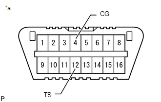 Text in Illustration
|
*a |
Front view of DLC3 |
(7) Check that the slip indicator light comes on.
(b) Perform zero point calibration of the yaw rate and acceleration sensor.
(1) Turn the ignition switch off.
(2) Check that the steering wheel is centered.
(3) Check that the shift lever is in P.
NOTICE:
- DTCs 36 (Zero Point Calibration of Yaw Rate Sensor Undone) and 39 (Zero Point Calibration of Acceleration Sensor Undone) are stored if the shift lever is not in P.
- If a DTC is output that indicates zero point calibration is incomplete, repeat the procedure starting at the step for clearing the zero point calibration data and system information.
(4) Using SST, connect terminals 12 (TS) and 4 (CG) of the DLC3.
SST: 09843-18040
Text in Illustration
|
*a |
Front view of DLC3 |
(5) Turn the ignition switch to ON.
(6) Keep the vehicle stationary on a level surface for 5 seconds or more.
(7) Check that the slip indicator light comes on for several seconds and then blink in the test mode pattern (0.125 seconds on and 0.125 seconds off).
HINT:
- If the slip indicator light does not blink, perform zero point calibration again.
- The zero point calibration is performed only once after the system enters test mode.
- Calibration cannot be performed again until the stored data is cleared.
(8) Turn the ignition switch off and disconnect SST from the DLC3.
(c) Drive the vehicle straight ahead at 40 km/h (25 mph) or more for at least 10 seconds.
4. PERFORM DOWNHILL ASSIST CONTROL CALIBRATION (w/ Downhill Assist Control)
(a) Enter test mode (when using the Techstream).
(1) Turn the ignition switch off.
(2) Connect the Techstream to the DLC3.
(3) Turn the ignition switch to ON.
(4) Turn the Techstream on.
(5) Enter the following menus: Chassis / ABS/VSC/TRAC / Utility / Test Mode.
(b) Enter test mode (when using SST check wire).
(1) Turn the ignition switch off.
(2) Using SST, connect terminals 12 (TS) and 4 (CG) of the DLC3.
SST: 09843-18040
Text in Illustration
|
*a |
Front view of DLC3 |
(3) Turn the ignition switch to ON.
(c) Turn the downhill assist control switch off.
(d) Push the downhill assist control switch and check that the downhill assist control indicator light is blinking.
(e) Turn the downhill assist control switch off.
(f) Turn the ignition switch off.
(g) Check if DTC C120A is output.
HINT:
If DTC C120A is not output, calibration was performed successfully.
5. PERFORM CRAWL CONTROL CALIBRATION (w/ Crawl Control)
(a) Enter test mode (when using the Techstream).
(1) Turn the ignition switch off.
(2) Connect the Techstream to the DLC3.
(3) Turn the ignition switch to ON.
(4) Turn the Techstream on.
(5) Enter the following menus: Chassis / ABS/VSC/TRAC / Utility / Test Mode.
(b) Enter test mode (when using SST check wire).
(1) Turn the ignition switch off.
(2) Using SST, connect terminals 12 (TS) and 4 (CG) of the DLC3.
SST: 09843-18040
Text in Illustration
|
*a |
Front view of DLC3 |
(3) Turn the ignition switch to ON.
(c) Push the crawl ON/OFF switch and check that the crawl indicator light is on while the switch is being pushed.
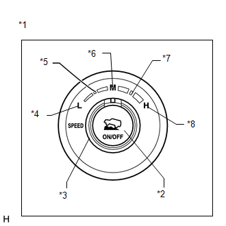 Text in Illustration
|
*1 |
Crawl Control Switch |
|
*2 |
ON/OFF Switch |
|
*3 |
Speed Selector Switch |
|
*4 |
Low |
|
*5 |
Medium-low |
|
*6 |
Medium |
|
*7 |
Medium-high |
|
*8 |
High |
(d) Turn the crawl ON/OFF switch off.
(e) Turn the speed selector switch to L (low).
(f) Turn the speed selector switch to medium-low.
(g) Turn the speed selector switch to M (medium).
(h) Turn the speed selector switch to medium-high.
(i) Turn the speed selector switch to H (high).
(j) Turn the speed selector switch to L (low).
(k) Turn the ignition switch off.
(l) Check if DTC C120A is output.
HINT:
If DTC C120A is not output, calibration was performed successfully.
 How To Proceed With Troubleshooting
CAUTION / NOTICE / HINT
HINT:
*: Use the Techstream.
PROCEDURE
1.
VEHICLE BROUGHT TO WORKSHOP
NEXT
...
 Test Mode Procedure
TEST MODE PROCEDURE
NOTICE:
After replacing the master cylinder solenoid and/or yaw rate and acceleration
sensor, perform calibration.
VSC is prohibited during test mode.
H ...
Other materials about Toyota 4Runner:
Certification ECU Power Source Circuit
DESCRIPTION
This circuit provides power to the certification ECU.
WIRING DIAGRAM
CAUTION / NOTICE / HINT
NOTICE:
Inspect the fuses for circuits related to this system before performing the following
inspection procedure.
PROCEDURE
1.
...
Reassembly
REASSEMBLY
PROCEDURE
1. INSTALL BACK DOOR UPPER DAMPER STAY BRACKET LH
2. INSTALL BACK DOOR UPPER DAMPER STAY BRACKET RH
HINT:
Use the same procedure as for the LH side.
3. INSTALL BACK DOOR STAY BOLT (for LH Side)
4. INSTALL BACK DOOR STAY BOLT ( ...

0.0074