Toyota 4Runner: Ultrasonic Sensor(for Front)
Components
COMPONENTS
ILLUSTRATION
ILLUSTRATION
Removal
REMOVAL
PROCEDURE
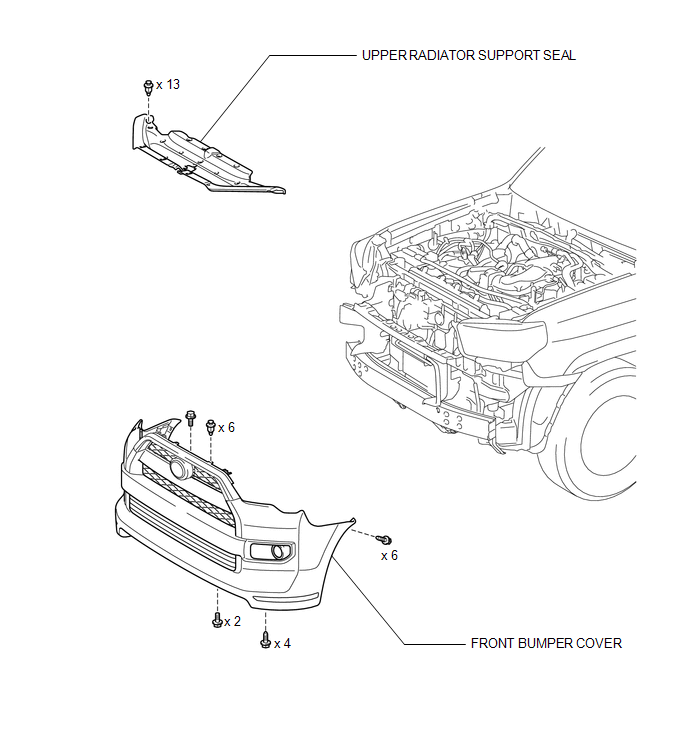
1. REMOVE UPPER RADIATOR SUPPORT SEAL
.gif)
2. REMOVE FRONT BUMPER COVER
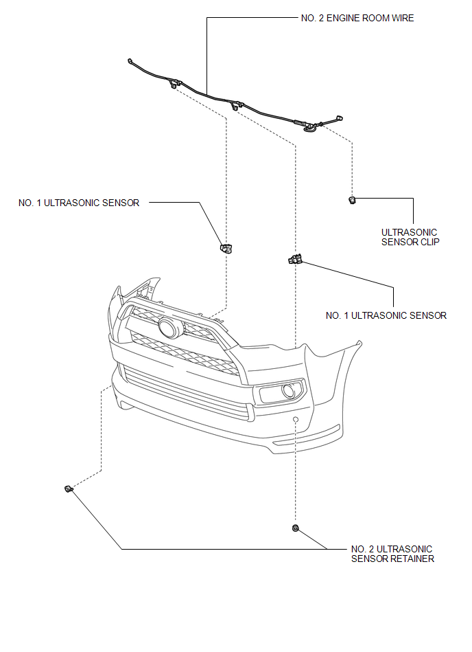
3. REMOVE NO. 2 ENGINE ROOM WIRE
4. REMOVE NO. 1 ULTRASONIC SENSOR
|
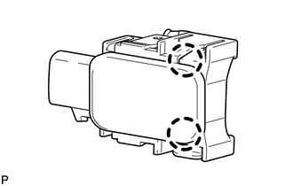
(a) Detach the 2 claws to remove the No. 1 ultrasonic sensor from the No. 2 ultrasonic sensor retainer. HINT: Use the same procedure as for the other side. |
|
5. REMOVE ULTRASONIC SENSOR CLIP
|
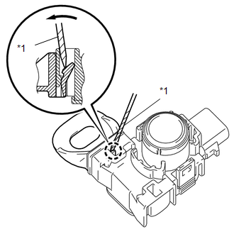
(a) Using a screwdriver, detach the claw to remove the ultrasonic sensor clip from the No. 1 ultrasonic sensor as shown in the illustration. Text in Illustration
HINT: Tape the screwdriver tip before use. |
|
6. REMOVE NO. 2 ULTRASONIC SENSOR RETAINER
|
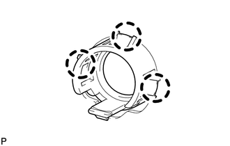
(a) Detach the 3 claws to remove the No. 2 ultrasonic sensor retainer from the front bumper cover. HINT: Use the same procedure as for the other side. |
|
Inspection
INSPECTION
PROCEDURE
1. INSPECT NO. 1 ULTRASONIC SENSOR
|
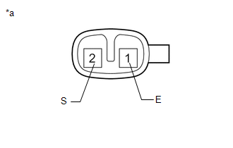
(a) Measure the resistance according to the value(s) in the table below. Standard Resistance:
If the result is not as specified, replace the No. 1 ultrasonic sensor. |
|
Installation
INSTALLATION
PROCEDURE
1. INSTALL NO. 2 ULTRASONIC SENSOR RETAINER
|
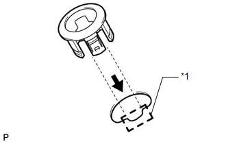
(a) Align the keyhole and protrusion as shown in the illustration. Text in Illustration
|
|
(b) Attach the 3 claws to install the No. 2 ultrasonic sensor retainer to the front bumper cover.
NOTICE:
Do not damage the front bumper cover with the protrusion when installing the No. 2 ultrasonic sensor retainer.
HINT:
Use the same procedure as for the other side.
2. INSTALL ULTRASONIC SENSOR CLIP
(a) Attach the claw to install the ultrasonic sensor clip to the No. 1 ultrasonic sensor.
3. INSTALL NO. 1 ULTRASONIC SENSOR
(a) Attach the 2 claws to install the No. 1 ultrasonic sensor to the No. 2 ultrasonic sensor retainer.
HINT:
Use the same procedure as for the other side.
4. INSTALL NO. 2 ENGINE ROOM WIRE
.gif)
5. INSTALL FRONT BUMPER COVER
6. INSTALL UPPER RADIATOR SUPPORT SEAL
 Television Camera(for Rear)
Components
COMPONENTS
ILLUSTRATION
Removal
REMOVAL
PROCEDURE
1. REMOVE ASSIST STRAP HOLE COVER
2. REMOVE ASSIST STRAP ASSEMBLY
3. REMOVE BACK DOOR TRIM PANEL ASSEMBLY
4. REMOVE ...

Other materials about Toyota 4Runner:
Reassembly
REASSEMBLY
CAUTION / NOTICE / HINT
NOTICE:
Do not allow foreign matter, etc. to contact the rear axle hub and bearing assembly.
PROCEDURE
1. INSTALL BRAKE DRUM OIL DEFLECTOR LH
(a) Install a new deflector gasket and deflector to the rear axle shaft.
H ...
System Diagram
SYSTEM DIAGRAM
w/ Smart Key System
No.
ECU/Sensor Name
1
Combination meter assembly
2
Skid control ECU (master cylinder solenoid)*1
3
Main body ECU (mu ...

0.0272