Toyota 4Runner: Television Camera(for Rear)
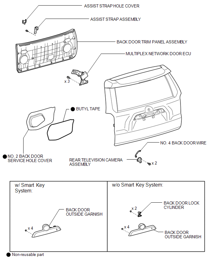
Components
COMPONENTS
ILLUSTRATION
Removal
REMOVAL
PROCEDURE
1. REMOVE ASSIST STRAP HOLE COVER
.gif)
2. REMOVE ASSIST STRAP ASSEMBLY
3. REMOVE BACK DOOR TRIM PANEL ASSEMBLY
4. REMOVE MULTIPLEX NETWORK DOOR ECU
5. REMOVE NO. 2 BACK DOOR SERVICE HOLE COVER
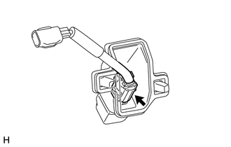
6. REMOVE BACK DOOR LOCK CYLINDER (w/o Smart Key System)
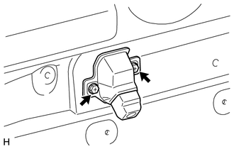
7. REMOVE BACK DOOR OUTSIDE GARNISH
8. REMOVE REAR TELEVISION CAMERA ASSEMBLY
|
(a) Remove the 2 screws. |
|
|
(b) Disconnect the connector. |
|
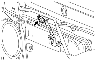
(c) Detach the 2 claws and remove the rear television camera assembly.
9. REMOVE NO. 4 BACK DOOR WIRE
(a) Disconnect the connector and remove the No. 4 back door wire.
Installation
INSTALLATION
PROCEDURE
1. INSTALL NO. 4 BACK DOOR WIRE
(a) Connect the connector to install the No. 4 back door wire.
2. INSTALL REAR TELEVISION CAMERA ASSEMBLY
(a) Attach the 2 claws to install the rear television camera assembly.
(b) Connect the connector.
(c) Install the 2 screws.
3. INSTALL BACK DOOR OUTSIDE GARNISH
.gif)
4. INSTALL BACK DOOR LOCK CYLINDER (w/o Smart Key System)
5. INSTALL NO. 2 BACK DOOR SERVICE HOLE COVER
6. INSTALL MULTIPLEX NETWORK DOOR ECU
7. INSTALL BACK DOOR TRIM PANEL ASSEMBLY
8. INSTALL ASSIST STRAP ASSEMBLY
9. INSTALL ASSIST STRAP HOLE COVER
 Image from Camera for Rear View Monitor is Abnormal
DESCRIPTION
The display signal from the rear television camera assembly transmits to the
radio and display receiver assembly.
WIRING DIAGRAM
PROCEDURE
1.
CHECK HARNESS A ...
 Ultrasonic Sensor(for Front)
Components
COMPONENTS
ILLUSTRATION
ILLUSTRATION
Removal
REMOVAL
PROCEDURE
1. REMOVE UPPER RADIATOR SUPPORT SEAL
2. REMOVE FRONT BUMPER COVER
3. REMOVE NO. 2 ENGINE ROOM WIRE
...
Other materials about Toyota 4Runner:
Installation
INSTALLATION
CAUTION / NOTICE / HINT
CAUTION:
Wear protective gloves. Sharp areas on the parts may injure your hands.
HINT:
A bolt without a torque specification is shown in the standard bolt chart (See
page ).
PROCEDURE
1. INSTALL REAR NO. 1 SEAT IN ...
Diagnosis System
DIAGNOSIS SYSTEM
1. DIAGNOSIS SYSTEM
(a) Indicator light
(1) During vehicle stabilizer control operation, the KDSS indicator light comes
on when there is a malfunction in the KDSS.
NOTICE:
When the malfunction has been corrected, the KDSS indica ...

0.0232