Toyota 4Runner: Voice Recognition Microphone Disconnected (B1579)
DESCRIPTION
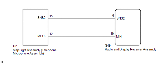
The radio and display receiver assembly and map light assembly (telephone microphone assembly) are connected to each other using the microphone connection detection signal lines.
This DTC is stored when a microphone connection detection signal line is disconnected.
|
DTC Code |
DTC Detection Condition |
Trouble Area |
|---|---|---|
|
B1579 |
Telephone microphone signal is lost. |
|
WIRING DIAGRAM
PROCEDURE
|
1. |
INSPECT RADIO AND DISPLAY RECEIVER ASSEMBLY |
|
(a) Measure the resistance according to the value(s) in the table below. Standard Resistance:
|
|
| NG | .gif) |
REPLACE RADIO AND DISPLAY RECEIVER ASSEMBLY |
|
.gif)
|
2. |
CHECK HARNESS AND CONNECTOR (RADIO AND DISPLAY RECEIVER ASSEMBLY - MAP LIGHT ASSEMBLY (TELEPHONE MICROPHONE ASSEMBLY)) |
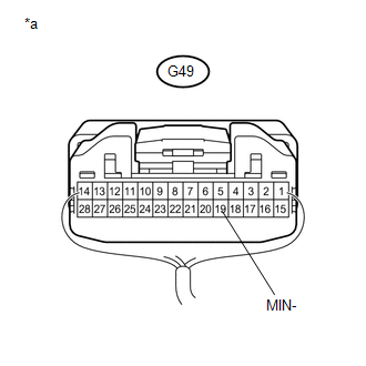
(a) Disconnect the G49 radio and display receiver assembly connector.
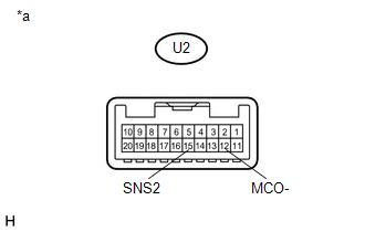
(b) Disconnect the U2 map light assembly (telephone microphone assembly) connector.
(c) Measure the resistance according to the value(s) in the table below.
Standard Resistance:
|
Tester Connection |
Condition |
Specified Condition |
|---|---|---|
|
G49-6 (SNS2) - U2-15 (SNS2) |
Always |
Below 1 Ω |
|
G49-19 (MIN-) - U2-12 (MCO-) |
Always |
Below 1 Ω |
|
G49-6 (SNS2) - Body ground |
Always |
10 kΩ or higher |
|
G49-19 (MIN-) - Body ground |
Always |
10 kΩ or higher |
| NG | |
REPAIR OR REPLACE HARNESS OR CONNECTOR |
|
|
3. |
INSPECT MAP LIGHT ASSEMBLY (TELEPHONE MICROPHONE ASSEMBLY) |
|
(a) Measure the resistance according to the value(s) in the table below. Standard Resistance:
|
|
| OK | |
REPLACE RADIO AND DISPLAY RECEIVER ASSEMBLY |
|
|
4. |
REPLACE TELEPHONE MICROPHONE ASSEMBLY |
(a) Replace the telephone microphone assembly (See page
.gif) ).
).
(b) Clear the DTCs (See page ).
(c) Recheck for DTCs and check if the same DTC is output again.
OK:
No DTCs are output.
| OK | |
END |
| NG | |
REPLACE MAP LIGHT ASSEMBLY (TELEPHONE MICROPHONE ASSEMBLY) |
 USB Device Malfunction (B1585)
DESCRIPTION
This DTC is stored when a malfunction occurs in a connected device.
DTC No.
DTC Detection Condition
Trouble Area
B1585
USB De ...
 LVDS Signal Malfunction (from Extension Module) (B1532)
DESCRIPTION
DTC No.
DTC Detection Condition
Trouble Area
B1532
When one of the conditions below is met:
Stereo component tun ...
Other materials about Toyota 4Runner:
Problem Symptoms Table
PROBLEM SYMPTOMS TABLE
HINT:
Use the table below to help determine the cause of problem symptoms.
If multiple suspected areas are listed, the potential causes of the symptoms
are listed in order of probability in the "Suspected Area" ...
Terminals Of Ecu
TERMINALS OF ECU
1. CHECK NO. 1 AIR CONDITIONING AMPLIFIER ASSEMBLY
(a) Disconnect the F42 No. 1 air conditioning amplifier assembly connector.
(b) Measure the voltage and resistance according to the value(s) in the table
below.
Terminal No. ...

0.0094