Toyota 4Runner: Washer Nozzle(for Front Side)
Components
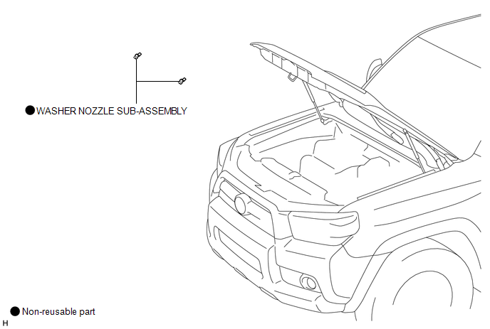
COMPONENTS
ILLUSTRATION
On-vehicle Inspection
ON-VEHICLE INSPECTION
PROCEDURE
1. INSPECT WASHER NOZZLE SUB-ASSEMBLY
(a) With the engine running, check the position that the washer fluid hits the windshield.
Standard:
Washer fluid hits the windshield in the areas shown in the illustration.
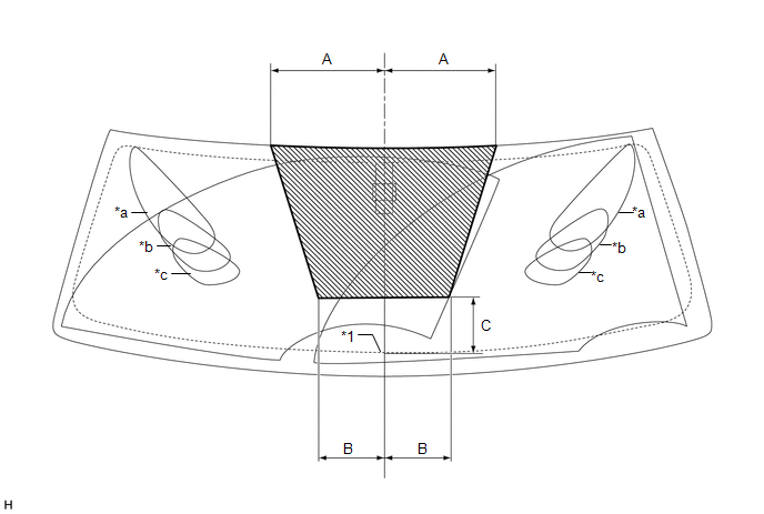 Text in Illustration
|
*1 |
Ceramic Line |
- |
- |
|
*a |
Upper Limit |
*b |
Standard |
|
*c |
Lower Limit |
- |
- |
.png) |
Washer Fluid Spray Area |
- |
- |
Standard:
|
Area |
Measurement |
Area |
Measurement |
|---|---|---|---|
|
A |
254.5 mm (10.0 in.) |
B |
150 mm (5.91 in.) |
|
C |
127.6 mm (5.02 in.) |
- |
- |
If the result is not as specified, replace the malfunctioning washer nozzle sub-assembly.
Removal
REMOVAL
PROCEDURE
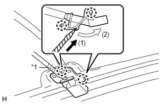
1. REMOVE WASHER NOZZLE SUB-ASSEMBLY
|
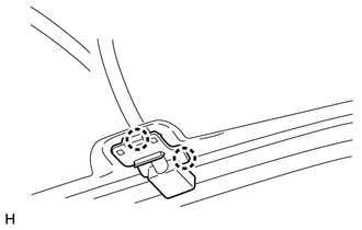
(a) Using a screwdriver, detach the 2 claws and disconnect the washer nozzle sub-assembly as shown in the illustration. HINT: Tape the screwdriver tip before use. Text in Illustration
NOTICE: Be careful not to damage the windshield. |
|
|
(b) Remove the washer nozzle sub-assembly from the washer hose. NOTICE: Washer nozzles cannot be reused. |
|
Adjustment
ADJUSTMENT
PROCEDURE
1. REMOVE WASHER NOZZLE SUB-ASSEMBLY
.gif)
2. ADJUST WASHER NOZZLE SUB-ASSEMBLY
(a) Select a washer nozzle so that the washer fluid spray area is as specified in On-vehicle Inspection. Replace the washer nozzle with the selected one.
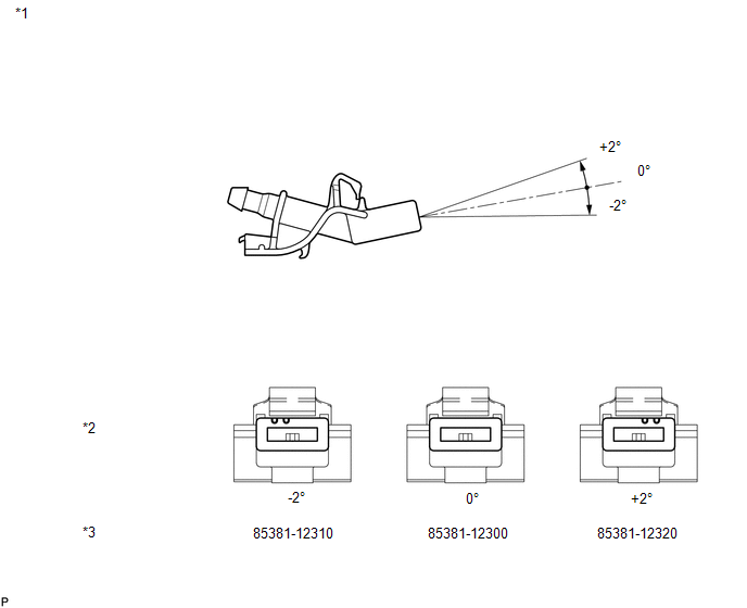 Text in Illustration
|
*1 |
Available Washer Nozzles |
*2 |
Washer Fluid Spray Angle |
|
*3 |
Part Number |
- |
- |
3. INSTALL WASHER NOZZLE SUB-ASSEMBLY
Installation
INSTALLATION
PROCEDURE
1. INSTALL WASHER NOZZLE SUB-ASSEMBLY
(a) Connect a new washer nozzle sub-assembly to the washer hose.
|
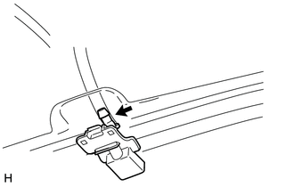
(b) Attach the 2 claws to install the washer nozzle sub-assembly. |
|
2. INSPECT WASHER NOZZLE SUB-ASSEMBLY
.gif)
3. ADJUST WASHER NOZZLE SUB-ASSEMBLY
 Washer Motor(for Rear Side)
Components
COMPONENTS
ILLUSTRATION
Removal
REMOVAL
PROCEDURE
1. DISCONNECT CABLE FROM NEGATIVE BATTERY TERMINAL
NOTICE:
When disconnecting the cable, some systems need to be initialized ...
 Washer Nozzle(for Rear Side)
Components
COMPONENTS
ILLUSTRATION
On-vehicle Inspection
ON-VEHICLE INSPECTION
CAUTION / NOTICE / HINT
HINT:
The washer fluid does not spray if the back door and back door glass are not
...
Other materials about Toyota 4Runner:
Calibration
CALIBRATION
1. DESCRIPTION
(a) After replacing VSC-related components, clearing and reading the sensor calibration
data is necessary.
(b) Follow the chart to perform calibration.
Part Replaced
Necessary Operation
Ma ...
Transmitter Battery(w/o Smart Key System)
Replacement
REPLACEMENT
CAUTION / NOTICE / HINT
NOTICE:
Take extra care when handling these precision electronic components.
PROCEDURE
1. REMOVE TRANSMITTER HOUSING COVER
(a) Twist a screwdriver in the direction of the arrow in the illustra ...

0.01