Toyota 4Runner: Washer Motor(for Rear Side)
Components
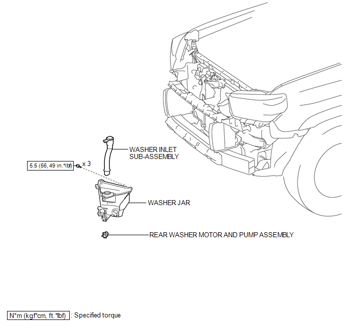
COMPONENTS
ILLUSTRATION
Removal
REMOVAL
PROCEDURE
1. DISCONNECT CABLE FROM NEGATIVE BATTERY TERMINAL
NOTICE:
When disconnecting the cable, some systems need to be initialized after the cable
is reconnected (See page .gif) ).
).
2. REMOVE FRONT BUMPER COVER (w/o Intuitive Parking Assist System)
(See page )
3. REMOVE FRONT BUMPER COVER (w/ Intuitive Parking Assist System)
(See page )
4. REMOVE FRONT FENDER LINER RH
(See page )
5. DRAIN WINDSHIELD WASHER FLUID
6. REMOVE WASHER INLET SUB-ASSEMBLY
7. REMOVE WASHER JAR
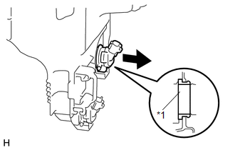
8. REMOVE REAR WASHER MOTOR AND PUMP ASSEMBLY
|
(a) Remove the rear washer motor and pump assembly from the packing of the washer jar. Text in Illustration
|
|
Inspection
INSPECTION
PROCEDURE
1. INSPECT REAR WASHER MOTOR AND PUMP ASSEMBLY
(a) Remove the washer jar.
(b) Disconnect the rear washer motor and pump connector.
HINT:
Make sure that the rear washer motor and pump is installed to the washer jar.
(c) Fill the washer jar with washer fluid.
|
(d) Connect the positive (+) lead of the battery to terminal 1 of the rear washer motor and pump and the negative (-) lead to terminal 2. |
|
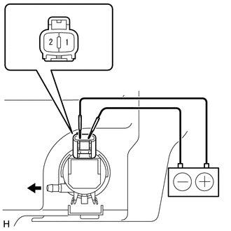
(e) Check that washer fluid flows from the washer jar.
OK:
Washer fluid flows from the washer jar.
If the result is not as specified, replace the rear washer motor and pump assembly.
Installation
INSTALLATION
PROCEDURE
1. INSTALL REAR WASHER MOTOR AND PUMP ASSEMBLY
(a) Install the rear washer motor and pump assembly to the packing of the washer jar.
2. INSTALL WASHER JAR
.gif)
3. INSTALL WASHER INLET SUB-ASSEMBLY
4. FILL WINDSHIELD WASHER FLUID
5. INSTALL FRONT FENDER LINER RH
(See page )
6. INSTALL FRONT BUMPER COVER (w/ Intuitive Parking Assist System)
(See page )
7. INSTALL FRONT BUMPER COVER (w/o Intuitive Parking Assist System)
(See page )
8. CONNECT CABLE TO NEGATIVE BATTERY TERMINAL
NOTICE:
When disconnecting the cable, some systems need to be initialized after the cable
is reconnected (See page ).
9. ADJUST FOG LIGHT AIMING
(See page )
 Installation
INSTALLATION
PROCEDURE
1. INSTALL WINDSHIELD WASHER MOTOR AND PUMP ASSEMBLY
(a) Install the windshield washer motor and pump assembly to the packing of the
washer jar.
2. INSTALL WASHER JAR
...
 Washer Nozzle(for Front Side)
Components
COMPONENTS
ILLUSTRATION
On-vehicle Inspection
ON-VEHICLE INSPECTION
PROCEDURE
1. INSPECT WASHER NOZZLE SUB-ASSEMBLY
(a) With the engine running, check the position that the was ...
Other materials about Toyota 4Runner:
Initialization
INITIALIZATION
1. RESET MEMORY
NOTICE:
Perform Reset Memory (AT initialization) when replacing the automatic
transmission assembly, valve body assembly or any of the shift solenoid
valves.
Reset Memory can only be performed with the Tech ...
Removal
REMOVAL
CAUTION / NOTICE / HINT
HINT:
Use the same procedure for the RH and LH sides.
The procedure listed below is for the LH side.
PROCEDURE
1. DISCONNECT CABLE FROM NEGATIVE BATTERY TERMINAL
NOTICE:
When disconnecting the cable, som ...

0.0268