Toyota 4Runner: Adjustment
ADJUSTMENT
PROCEDURE
1. VEHICLE PREPARATION FOR FOG LIGHT AIM ADJUSTMENT
(a) Prepare the vehicle:
- Make sure that the vehicle has no damage or deformation around the headlights.
- Fill the fuel tank.
- Make sure that all of the different types of oil in the vehicle (engine oil, etc.) are filled to the specified levels.
- Make sure that the coolant is filled to the specified level.
- Inflate the tires to the appropriate pressure.
- Place the spare tire, tools, and jack in their original positions.
- Unload the trunk.
- Have a person that weighs approximately 68 kg (150 lb) sit in the driver seat.
2. PREPARATION FOR FOG LIGHT AIMING (Using a screen)
|
(a) Prepare the vehicle according to the following conditions: Text in Illustration
|
|
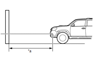
(b) Prepare a piece of thick white paper that is approximately 2 m (6.6 ft.) (height) x 4 m (13.1 ft.) (width) to use as a screen.
(c) Draw a vertical line down the center of the screen (V line).
(d) Set the screen as shown in the illustration.
HINT:
- Stand the screen perpendicular to the ground.
- Align the V line on the screen with the center of the vehicle.
|
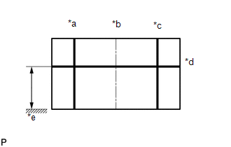
(e) Draw base lines (H line, V LH and V RH lines) on the screen as shown in the illustration. Text in Illustration
(1) H Line (fog light height): Draw a horizontal line across the screen so that it passes through the center marks. The H line should be at the same height as the fog light bulb center marks of the fog lights. (2) V LH Line, V RH Line (center mark position of LH and RH fog lights): Draw two vertical lines so that they intersect the H line at each center mark. |
|
3. INSPECT FOG LIGHT AIMING
(a) Choose a headlight to inspect first. Cover or disconnect the connector of the other fog light to prevent light from that fog light from affecting the fog light aiming inspection.
(b) Start the engine.
NOTICE:
The engine speed must be 1500 or more.
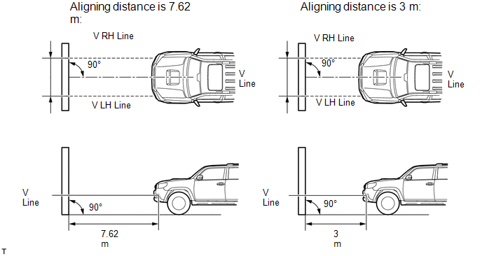
(c) Turn on the fog lights and make sure that the cutoff line is within the specified area shown in the illustration.
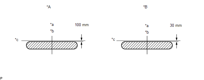 Text in Illustration
|
*A |
Aligning distance is 7.62 m |
*B |
Aligning distance is 3 m |
|
*a |
V LH Line |
*b |
V RH Line |
|
*c |
H Line |
- |
- |
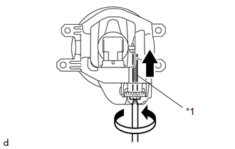
4. ADJUST FOG LIGHT AIMING
|
(a) Adjust the fog light aim into the specified range by turning the aiming screw with a screwdriver. Text in Illustration
NOTICE: If the screw is tightened too much, loosen it and then retighten it so that the final turn of the screw is in the clockwise direction. |
|
 Removal
REMOVAL
CAUTION / NOTICE / HINT
HINT:
Use the same procedure for both the RH and LH sides.
The procedure listed below is for the LH side.
PROCEDURE
1. REMOVE FRONT BUMPER COVER ...
 Reassembly
REASSEMBLY
CAUTION / NOTICE / HINT
HINT:
Use the same procedure for both the RH and LH sides.
The procedure listed below is for the LH side.
PROCEDURE
1. INSTALL FOG LIGHT BULB
...
Other materials about Toyota 4Runner:
Power Window Switch Malfunction (B2312)
DESCRIPTION
The power window regulator motor is driven by operating the power window regulator
switch. The power window regulator motor assembly consists of the motor and ECU.
This DTC is output when the ECU built into the regulator motor and master switch ...
Clearance Warning Buzzer
Components
COMPONENTS
ILLUSTRATION
Removal
REMOVAL
PROCEDURE
1. REMOVE INSTRUMENT PANEL SUB-ASSEMBLY
(a) Remove the instrument panel sub-assembly (See page
).
2. REMOVE NO. 1 CLEARANCE WARNING BUZZER
(a) Disconnect the connector.
(b) Detach ...
0.013