Toyota 4Runner: Air Outlet Damper Control Servo Motor Circuit (B1443)
DESCRIPTION
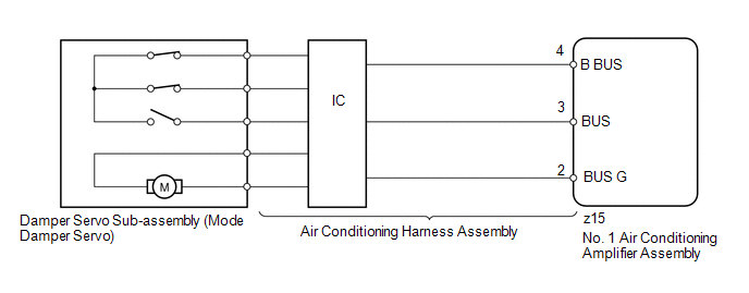
The damper servo sub-assembly (mode damper servo) sends pulse signals to inform the No. 1 air conditioning amplifier assembly of the damper position. The No. 1 air conditioning amplifier assembly activates the motor (normal or reverse) based on the signals to move the air outlet damper to any position, which controls the air outlet changes.
HINT:
Confirm that no mechanical problem is present because this trouble code may be stored when either a damper link or damper is mechanically locked.
|
DTC Code |
DTC Detection Condition |
Trouble Area |
|---|---|---|
|
B1443 |
The air outlet damper position does not change when the No. 1 air conditioning amplifier assembly operates the damper servo sub-assembly (mode damper servo). |
|
WIRING DIAGRAM
PROCEDURE
|
1. |
READ VALUE USING TECHSTREAM (MODE DAMPER SERVO) |
(a) Use the Data List to check if the damper servo sub-assembly (mode damper
servo) is functioning properly (See page .gif) ).
).
Air Conditioner
|
Tester Display |
Measurement Item/Range |
Normal Condition |
Diagnostic Note |
|---|---|---|---|
|
Air Outlet Servo Pulse (D) |
Damper servo sub-assembly (mode damper servo) actual pulse / Min.: 0, Max.: 255 |
15 (pulse): FACE 41 (pulse): B/L 65 or 73 (pulse): FOOT 83 or 95 (pulse): F/D 113 (pulse): DEF |
- |
|
Air Outlet Servo Actu Pulse (D) |
Damper servo sub-assembly (mode damper servo) actual pulse / Min.: 0, Max.: 255 |
15 (pulse): FACE 41 (pulse): B/L 65 or 73 (pulse): FOOT 83 or 95 (pulse): F/D 113 (pulse): DEF |
- |
OK:
The display is as specified in the normal condition column.
Result|
Result |
Proceed to |
|---|---|
|
OK (When troubleshooting according to problem symptoms table) |
A |
|
OK (When troubleshooting according to the DTC) |
B |
|
NG |
C |
| A | .gif) |
PROCEED TO NEXT SUSPECTED AREA SHOWN IN PROBLEM SYMPTOMS TABLE |
| B | |
REPLACE NO. 1 AIR CONDITIONING AMPLIFIER ASSEMBLY |
|
.gif)
|
2. |
PERFORM ACTIVE TEST USING TECHSTREAM (MODE DAMPER SERVO) |
(a) Select the Active Test, use the Techstream to generate a control command,
and then check that the damper servo sub-assembly (mode damper servo) operates (See
page ).
Air Conditioner
|
Tester Display |
Test Part |
Control Range |
Diagnostic Note |
|---|---|---|---|
|
Air Outlet Servo Pulse (D) |
Damper servo sub-assembly (mode damper servo) pulse |
Min.: 0, Max.: 255 |
- |
OK:
Damper servo sub-assembly (mode damper servo) operates normally.
| OK | |
REPLACE NO. 1 AIR CONDITIONING AMPLIFIER ASSEMBLY |
|
|
3. |
REPLACE DAMPER SERVO SUB-ASSEMBLY (MODE DAMPER SERVO) |
(a) Replace the damper servo sub-assembly (mode damper servo) (See page
).
HINT:
Since the damper servo sub-assembly (mode damper servo) cannot be inspected while it is removed from the vehicle, replace the damper servo sub-assembly (mode damper servo) with a new or normally functioning one.
|
|
4. |
CHECK FOR DTC |
(a) Clear the DTCs (See page ).
(b) Check for DTCs (See page ).
OK:
DTC B1443 is not output.
| OK | |
END (DAMPER SERVO SUB-ASSEMBLY [MODE DAMPER SERVO] IS FAULTY) |
|
|
5. |
REPLACE NO. 1 AIR CONDITIONING AMPLIFIER ASSEMBLY |
(a) Temporarily replace the No. 1 air conditioning amplifier assembly with a
new or normally functioning one (See page ).
|
|
6. |
CHECK FOR DTC |
(a) Clear the DTCs (See page ).
(b) Check for DTCs (See page ).
OK:
DTC B1443 is not output.
| OK | |
END (NO. 1 AIR CONDITIONING AMPLIFIER ASSEMBLY IS FAULTY) |
| NG | |
REPLACE AIR CONDITIONING HARNESS ASSEMBLY |
 Lost Communication with ECM (U0100,U0142,U0155)
DESCRIPTION
The air conditioning amplifier communicates with the ECM, main body ECU (multiplex
network body ECU) and combination meter through the CAN communication system.
DTC Code
...
 Communication Malfunction (Bus Ic) (B1497)
DESCRIPTION
The air conditioning harness assembly connects the No. 1 air conditioning amplifier
assembly and each servo motor. The No. 1 air conditioning amplifier assembly supplies
power and sen ...
Other materials about Toyota 4Runner:
Front Airbag Sensor LH Malfunction (B1615/14)
DESCRIPTION
The front airbag sensor LH consists of the diagnostic circuit and frontal deceleration
sensor, etc.
If the center airbag sensor receives signals from the frontal deceleration sensor,
it determines whether the SRS should be activated.
DTC B16 ...
How To Proceed With Troubleshooting
CAUTION / NOTICE / HINT
HINT:
Use these procedures to troubleshoot the automatic running board system.
PROCEDURE
1.
VEHICLE BROUGHT TO WORKSHOP
NEXT
...
0.0088