Toyota 4Runner: Communication Malfunction (Bus Ic) (B1497)
DESCRIPTION
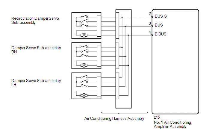
The air conditioning harness assembly connects the No. 1 air conditioning amplifier assembly and each servo motor. The No. 1 air conditioning amplifier assembly supplies power and sends operation instructions to each servo motor through the No. 1 air conditioning amplifier assembly. Each servo motor sends the damper position information to the No. 1 air conditioning amplifier assembly.
|
DTC Code |
DTC Detection Condition |
Trouble Area |
|---|---|---|
|
B1497 |
An open circuit or malfunction in the communication line. |
|
WIRING DIAGRAM
PROCEDURE
|
1. |
CHECK NO. 1 AIR CONDITIONING AMPLIFIER ASSEMBLY |
|
(a) Remove the No. 1 air conditioning amplifier assembly with its connectors
still connected (See page |
|
.gif) ).
).
(b) Measure the resistance according to the value(s) in the table below.
Standard Resistance:
|
Tester Connection |
Condition |
Specified Condition |
|---|---|---|
|
z15-2 (BUS G) - Body ground |
Always |
Below 1 Ω |
(c) Measure the voltage according to the value(s) in the table below.
Standard Voltage:
|
Tester Connection |
Switch Condition |
Specified Condition |
|---|---|---|
|
z15-2 (BUS G) - z15-4 (B BUS) |
Always |
11 to 14 V |
|
z15-2 (BUS G) - z15-3 (BUS) |
Ignition switch ON |
Pulse generation |
|
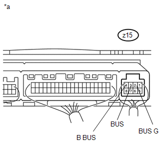
*a |
Component with harness connected (No. 1 Air Conditioning Amplifier Assembly) |
|
Result |
Proceed to |
|---|---|
|
OK (When troubleshooting according to problem symptoms table) |
A |
|
OK (When troubleshooting according to the DTC) |
B |
|
NG |
C |
| A | .gif) |
PROCEED TO NEXT SUSPECTED AREA SHOWN IN PROBLEM SYMPTOMS TABLE |
| B | |
REPLACE AIR CONDITIONING HARNESS ASSEMBLY |
| C | |
REPLACE NO. 1 AIR CONDITIONING AMPLIFIER ASSEMBLY |
 Air Outlet Damper Control Servo Motor Circuit (B1443)
DESCRIPTION
The damper servo sub-assembly (mode damper servo) sends pulse signals to inform
the No. 1 air conditioning amplifier assembly of the damper position. The No. 1
air conditioning amplif ...
 Air Inlet Damper Control Servo Motor Circuit (B1442)
DESCRIPTION
The recirculation damper servo sub-assembly sends pulse signals to inform the
No. 1 air conditioning amplifier assembly of the damper position. The No. 1 air
conditioning amplifier as ...
Other materials about Toyota 4Runner:
System Description
SYSTEM DESCRIPTION
1. GENERAL
(a) The heater and blower both have 3 levels controlled by operating the dial-type
refreshing seat switch, which is located in the upper console panel.
(b) The on/off state of the heater or blower can be determined by checkin ...
Security Horn Assembly
Components
COMPONENTS
ILLUSTRATION
Removal
REMOVAL
PROCEDURE
1. REMOVE AIR CLEANER CAP AND HOSE
2. REMOVE AIR CLEANER CASE SUB-ASSEMBLY
3. REMOVE SECURITY HORN ASSEMBLY
(a) Disconnect the connector.
...
0.013